Theoretical Paper
- Computer Organization
- Data Structure
- Digital Electronics
- Object Oriented Programming
- Discrete Mathematics
- Graph Theory
- Operating Systems
- Software Engineering
- Computer Graphics
- Database Management System
- Operation Research
- Computer Networking
- Image Processing
- Internet Technologies
- Micro Processor
- E-Commerce & ERP
Practical Paper
Industrial Training
Successive approximation method for A/D conversion
This type of converter is used to convert analog voltage to its corresponding digital output. The function of the analog to digital converter is exactly opposite to that of a DIGITAL TO ANALOG CONVERTER. Like a D/A converter, an A/D converter is also specified as 8, 10, 12 or 16 bit. Though there are many types of A/D converters, we will be discussing only about the successive approximation type.
Successive Approximation Type Analog to Digital Converter
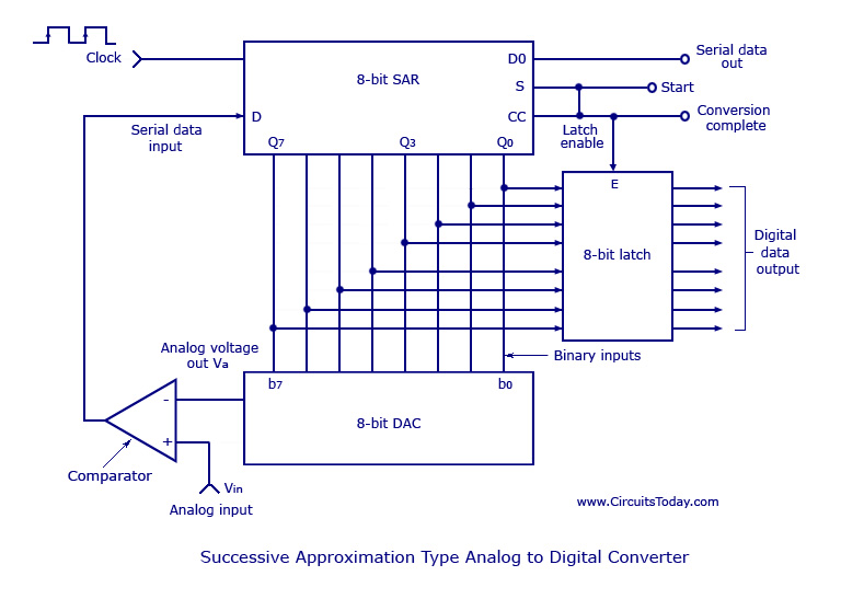
A successive approximation A/D converter consists of a comparator, a successive approximation register (SAR), output latches, and a D/A converter. The circuit diagram is shown below.

The main part of the circuit is the 8-bit SAR, whose output is given to an 8-bit D/A converter. The analog output Va of the D/A converter is then compared to an analog signal Vin by the comparator. The output of the comparator is a serial data input to the SAR. Till the digital output (8 bits) of the SAR is equivalent to the analog input Vin, the SAR adjusts itself. The 8-bit latch at the end of conversation holds onto the resultant digital data output.
Working
At the start of a conversion cycle, the SAR is reset by making the start signal (S) high. The MSB of the SAR (Q7) is set as soon as the first transition from LOW to HIGH is introduced. The output is given to the D/A converter which produces an analog equivalent of the MSB and is compared with the analog input Vin.
If comparator output is LOW, D/A output will be greater than Vin and the MSB will be cleared by the SAR.
If comparator output is HIGH, D/A output will be less than Vin and the MSB will be set to the next position (Q7 to Q6) by the SAR.
According to the comparator output, the SAR will either keep or reset the Q6 bit. This process goes on until all the bits are tried. After Q
is tried, the SAR makes the conversion complete (CC) signal HIGH to show that the parallel output lines contain valid data. The CC signal in turn enables the latch, and digital data appear at the output of the latch. As the SAR determines each bit, digital data is also available serially. As shown in the figure above, the CC signal is connected to the start conversion input in order to convert the cycle continuously.
The biggest advantage of such a circuit is its high speed. It may be more complex than an A/D converter, but it offers better resolution.

