Theoretical Paper
- Computer Organization
- Data Structure
- Digital Electronics
- Object Oriented Programming
- Discrete Mathematics
- Graph Theory
- Operating Systems
- Software Engineering
- Computer Graphics
- Database Management System
- Operation Research
- Computer Networking
- Image Processing
- Internet Technologies
- Micro Processor
- E-Commerce & ERP
Practical Paper
Industrial Training

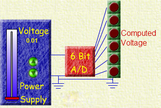
Counter based A/D converter
Analog-to-Digital converters - a.k.a. A/D converters - are widely used by many engineers and scientists of all types, often without their realizing it. Whenever they make a measurement of a voltage, and that measurement is taken into a computer, an A/D is used.
If you're going to take measurements - and just about every engineer will do a lot of that - then you will be better off if you understand some of the basic ideas behind A/D converters. There are two simple goals for this lesson.
Given an A/D converter with a given range and number of bits,
To be able to calculate the resolution of the converter.
Given an A/D converter in the laboratory,
To be able to determine the resolution of the converter and the number of bits used in the converter.
What Are A/D Converters?
A/D converters are electrical circuits that have the following characteristics.
The input to the A/D converter is a voltage.
A/D converters may be designed for voltages from 0 to 10v, from -5 to +5v, etc., but they almost always take a voltage input. (Some rare exceptions occur with current inputs!) In any event, the input is an analog voltage signal for most cases.
The output of the A/D converter is a binary signal, and that binary signal encodes the analog input voltage. So, the output is some sort of digital number.
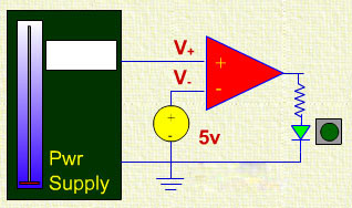
A comparator can be used as a simple one-bit A/D converter. Although a converter with just one bit isn't particularly useful, you can begin to see how an A/D converter works by puttering with it for a moment. If you read the lesson on comparators you encountered a simluation of a comparator. That simulator is reproduced below. Click here if you want to read the lesson on comparators.
Comparator Simulator
Sim1 Here is the comparator simulator. You can think of a comparator as a one-bit A/D converter. The input is an analog signal, and the output is a one bit digital representation of the analog signal. In the simulator, you can control a simulated voltage source that is the input the the comparator, and the digital output bit is indicated with a simulated LED. Notice the following.
The input can range from zero (0) to ten (10) volts.
When the input voltage goes above five (5) volts, the output is a binary one (1) and the LED lights. When the input voltage is less than five volts, the output is a binary zero (0) and the LED does not light.
Properties of A/D Converters
The comparator simulation reveals a few important facts about A/D converters.
An A/D converter has a range. The simulator has a range from 0v to 10v, or a total of ten (10) volts. The total range of an A/D is the difference between the highest and lowest voltages the A/D can convert.
An A/D has a resolution that is determined by the largest count that the A/D's counter/register can hold.
The largest count is determined by the number of bits in the counter.
If there are N bits in the counter, the largest count is 2N-1.
In the comparator, there is only one bit, and the largest count is 1, and there are only two different outputs that are possible.
Clearly, if you want a more accurate conversion the converter will need to have a lot more than just one bit. Let's look at another simulation. This simulation is a four-bit A/D converter.
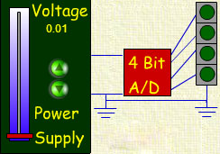
Four Bit A/D Converter Simulator
Sim2 Here is a simulation of a four bit A/D converter. Note the following:
As in the comparator simulation, we assume that the input voltage can range from zero (0) to ten (10) volts.
We have added some "fine control" with two buttons that "nudge" the voltage up or down, but not beyond the 0-10v range.
Try the simulator first, and then we will examine what happens in a little more detail.
Now, consider the following observations about the converter above.
There are four bits in the simulation converter.
The range is from 0v to 10v, or 10v total range.
With four bits, there are 16 different count values (0 through 15).
Thus, 10v is divided into 16 different parts, each part being:
10/16 = 0.625 volts wide.
Now, let's consider an example question.
Four Bit A/D Converter Simulator (Revised)
Sim3 Here is a revised simulation of a four bit A/D converter. Note the following:
Vmeas = Count*0.625
Vmeas is displayed on the simulation.
Of course, the simulation only raises a few more issues.
The largest issue is that the computed voltage is always lower than the actual voltage.
The average error would probably be less if we used a different way to compute the computed voltage.
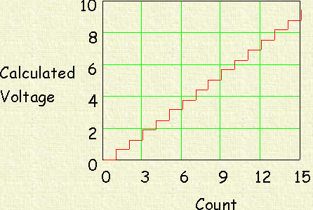
The formula for the computed voltage is:
Vmeas = Count*0.625
Using this expression for the calculated voltage, we can plot the calculated voltage as a function of the count. That's shown in the figure below.
Even more interesting is the plot of the calculated voltage against the voltage input that is being measured. That's shown next. We've also included a plot (the blue line) that shows what the output would be ideally (And that might take many, many bits in the converter!). Notice that the calculated voltage is always lower than the voltage input using the calculation method we assumed above. Note also that the largest error occurs just before the converter switches when the voltage is rising. For example, as the voltage rises from 0v to 3v, there is a time when the converter output switches from 0v to 0.625v. The largest error occurs just before that point, so a bound on the
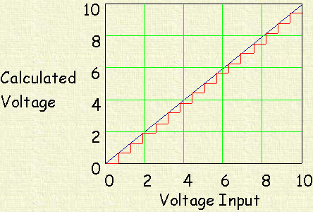
Whenever you buy an A/D converter, or a voltmeter, or a data acquisition unit, you need to be cognizant of how the data presented to the user is actually computed. That's not usually a problem in instruments, but there are A/D computer cards that use the first method above to calculate voltage, and you should be aware of that when it happens. It is less important when the number of bits in the converter is higher, but when you have high requirements for accuracty you should be thinking of what might be taking place.
If there are N bits, the number of divisions is 2N-1.
If the total range of voltage is VRange, then the size of a division is:
SmallestDivision = VRange/2N
The error is related to the Division size.
If the calculated voltage is SmallestDivision*Count, the error is the same size as the smallest division.
If the calculated voltage is SmallestDivision*Count + SmallestDivision/2, the error is SmallestDivision/2, i.e. half the size of the smallest division.
See the simulations above for a better appreciation/understanding of the error.
We're not going to give you any more simulators with more bits. Actually, we've almost reached the resolution limit for the screen. The simulators with the "nudge buttons" just nudge the controls by a single pixel, and that is too much for a twelve bit converter, for example.