Theoretical Paper
- Computer Organization
- Data Structure
- Digital Electronics
- Object Oriented Programming
- Discrete Mathematics
- Graph Theory
- Operating Systems
- Software Engineering
- Computer Graphics
- Database Management System
- Operation Research
- Computer Networking
- Image Processing
- Internet Technologies
- Micro Processor
- E-Commerce & ERP
Practical Paper
Industrial Training

Excitation Functions Each Flip Flops
Since memory elements in sequential circuits are usually flip-flops, it is worth summarizing the behavior of various flip-flop types before proceeding further. All flip-flops can be divided into four basic types: SR, JK, D and T. They differ in the number of inputs and in the response invoked by different value of input signals. The four types of flip-flops are defined in Table 1.
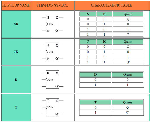
Each of these flip-flops can be uniquely described by its graphical symbol, its characteristic table, its characteristic equation or excitation table. All flip-flops have output signals Q and Q'.
The characteristic table in the third column of Table 1 defines the state of each flip-flop as a function of its inputs and previous state. Q refers to the present state and Q(next) refers to the next state after the occurrence of the clock pulse. The characteristic table for the RS flip-flop shows that the next state is equal to the present state when both inputs S and R are equal to 0. When R=1, the next clock pulse clears the flip-flop. When S=1, the flip-flop output Q is set to 1. The equation mark (?) for the next state when S and R are both equal to 1 designates an indeterminate next state.
The characteristic table for the JK flip-flop is the same as that of the RS when J and K are replaced by S and R respectively, except for the indeterminate case. When both J and K are equal to 1, the next state is equal to the complement of the present state, that is, Q(next) = Q'.
The next state of the D flip-flop is completely dependent on the input D and independent of the present state.
The next state for the T flip-flop is the same as the present state Q if T=0 and complemented if T=1.
The characteristic table is useful during the analysis of sequential circuits when the value of flip-flop inputs are known and we want to find the value of the flip-flop output Q after the rising edge of the clock signal. As with any other truth table, we can use the map method to derive the characteristic equation for each flip-flop, which are shown in the third column of Table 1.
During the design process we usually know the transition from present state to the next state and wish to find the flip-flop input conditions that will cause the required transition. For this reason we will need a table that lists the required inputs for a given change of state. Such a list is called the excitation table, which is shown in the fourth column of Table 1. There are four possible transitions from present state to the next state. The required input conditions are derived from the information available in the characteristic table. The symbol X in the table represents a "don't care" condition, that is, it does not matter whether the input is 1 or 0.