Theoretical Paper
- Computer Organization
- Data Structure
- Digital Electronics
- Object Oriented Programming
- Discrete Mathematics
- Graph Theory
- Operating Systems
- Software Engineering
- Computer Graphics
- Database Management System
- Operation Research
- Computer Networking
- Image Processing
- Internet Technologies
- Micro Processor
- E-Commerce & ERP
Practical Paper
Industrial Training

Digital to Analog Converter using Binary-Weighted Resistors
In electronics, a digital-to-analog converter (DAC, D/A, D2A or D-to-A) is a function that converts digital data (usually binary) into ananalog signal (current, voltage, or electric charge). An analog-to-digital converter (ADC) performs the reverse function. Unlike analog signals,digital data can be transmitted, manipulated, and stored without degradation, albeit with more complex equipment. But a DAC is needed to convert the digital signal to analog to drive an earphone or loudspeaker amplifier in order to produce sound (analog air pressure waves).
DACs and their inverse, ADCs, are part of an enabling technology that has contributed greatly to the digital revolution. To illustrate, consider a typical long-distance telephone call. The caller's voice is converted into an analog electrical signal by a microphone, then the analog signal is converted to a digital stream by an ADC. The digital stream is then divided into packets where it may be mixed with other digital data, not necessarily audio. The digital packets are then sent to the destination, but each packet may take a completely different route and may not even arrive at the destination in the correct time order. The digital voice data is then extracted from the packets and assembled into a digital data stream. A DAC converts this into an analog electrical signal, which drives an audio amplifier, which in turn drives a loudspeaker, which finally produces sound.
There are several DAC architectures; the suitability of a DAC for a particular application is determined by six main parameters: physical size, power consumption, resolution, speed, accuracy, cost. Due to the complexity and the need for precisely matched components, all but the most specialist DACs are implemented as integrated circuits (ICs). Digital-to-analog conversion can degrade a signal, so a DAC should be specified that has insignificant errors in terms of the application.
DACs are commonly used in music players to convert digital data streams into analog audio signals. They are also used in televisions and mobile phones to convert digital video data into analog video signals which connect to the screen drivers to display monochrome or color images. These two applications use DACs at opposite ends of the speed/resolution trade-off. The audio DAC is a low speed high resolution type while the video DAC is a high speed low to medium resolution type. Discrete DACs would typically be extremely high speed low resolution power hungry types, as used in military radar systems. Very high speed test equipment, especially sampling oscilloscopes, may also use discrete DACs.
A D/A converter using binary-weighted resistors is shown in the figure below. In the circuit, the op-amp is connected in the inverting mode. The op-amp can also be connected in the non-inverting mode. The circuit diagram represents a 4-digit converter. Thus, the number of binary inputs is four.
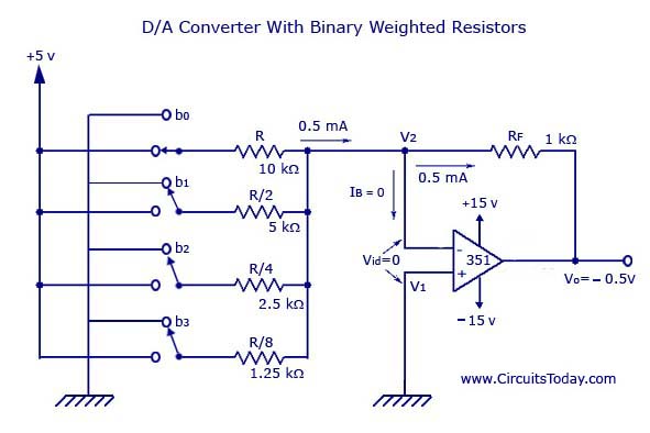
We know that, a 4-bit converter will have 24 = 16 combinations of output. Thus, a corresponding 16 outputs of analog will also be present for the binary inputs.
Four switches from b0 to b3 are available to simulate the binary inputs: in practice, a 4-bit binary counter such as a 7493 can also be used.
Working
The circuit is basically working as a current to voltage converter.
b0 is closed
It will be connected directly to the +5V.
Thus, voltage across R = 5V
Current through R = 5V/10kohm = 0.5mA
Current through feedback resistor, Rf = 0.5mA (Since, Input bias current, IB is negligible)
Thus, output voltage = -(1kohm)*(0.5mA) = -0.5V
b1 is closed, b0 is open
R/2 will be connected to the positive supply of the +5V.
Current through R will become twice the value of current (1mA) to flow through Rf.
Thus, output voltage also doubles.
b0 and b1 are closed
Current through Rf = 1.5mA
Output voltage = -(1kohm)*(1.5mA) = -1.5V
Thus, according to the position (ON/OFF) of the switches (bo-b3), the corresponding “binary-weighted” currents will be obtained in the input resistor. The current through Rf will be the sum of these currents. This overall current is then converted to its proportional output voltage. Naturally, the output will be maximum if the switches (b0-b3) are closed
V0 = -Rf *([b0/R][b1/(R/2)][b2/(R/4)][b3/(R/8)]) – where each of the inputs b3, b2, b1, and b0 may either be HIGH (+5V) or LOW (0V).
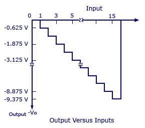
The graph with the analog outputs versus possible combinations of inputs is shown below.
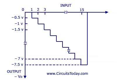
The output is a negative going staircase waveform with 15 steps of -).5V each. In practice, due to the variations in the logic HIGH voltage levels, all the steps will not have the same size. The value of the feedback resistor Rf changes the size of the steps. Thus, a desired size for a step can be obtained by connecting the appropriate feedback resistor. The only condition to look out for is that the maximum output voltage should not exceed the saturation levels of the op-amp. Metal-film resistors are more preferred for obtaining accurate outputs.
Disadvantages
If the number of inputs (>4) or combinations (>16) is more, the binary-weighted resistors may not be readily available. This is why; R and 2R method is more preferred as it requires only two sets of precision resistance values.
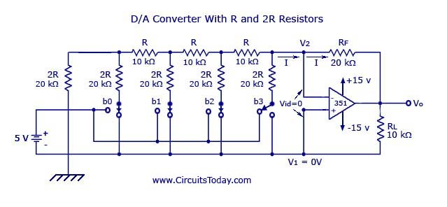
2. Digital to Analog Converter with R and 2R Resistors
A D/A converter with R and 2R resistors is shown in the figure below. As in the binary-weighted resistors method, the binary inputs are simulated by the switches (b0-b3), and the output is proportional to the binary inputs. Binary inputs can be either in the HIGH (+5V) or LOW (0V) state. Let b3 be the most significant bit and thus is connected to the +5V and all the other switchs are connected to the ground.
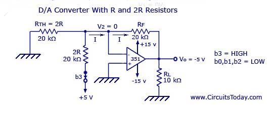
Thus, according to Thevenin’s equivalent resistance, RTH,
RTH = [{[(2RII2R + R)} II2R] + R}II2R] + R = 2R = 20kOhms.
The resultant circuit is shown below.
Graph is given below.
In the figure shown above, the negative input is at virtual ground, therefore the current through RTH=0.
Current through 2R connected to +5V = 5V/20kohm = 0.25 mA
The current will be the same as that in Rf.
Vo = -(20kohm)*(0.25mA) = -5V
Output voltage equation is given below.
V0 = -Rf (b3/2R+b2/4R+b1/8R+b0/16R)