Theoretical Paper
- Computer Organization
- Data Structure
- Digital Electronics
- Object Oriented Programming
- Discrete Mathematics
- Graph Theory
- Operating Systems
- Software Engineering
- Computer Graphics
- Database Management System
- Operation Research
- Computer Networking
- Image Processing
- Internet Technologies
- Micro Processor
- E-Commerce & ERP
Practical Paper
Industrial Training

DTL and TTL NAND gate circuits and its operations
Transistor–transistor logic (TTL) is a class of digital circuits built from bipolar junction transistors (BJT) and resistors. It is called transistor–transistor logic because both the logic gating function (e.g., AND) and the amplifying function are performed by transistors (contrast with RTL and DTL).
TTL is notable for being a widespread integrated circuit (IC) family used in many applications such as computers, industrial controls, test equipment and instrumentation, consumer electronics, synthesizers, etc. The designation TTL is sometimes used to mean TTL-compatible logic levels, even when not associated directly with TTL integrated circuits, for example as a label on the inputs and outputs of electronic instruments.
After their introduction in integrated circuit form in 1963 by Sylvania, TTL integrated circuits were manufactured by several semiconductor companies, with the 7400 series by Texas Instruments becoming particularly popular. TTL manufacturers offered a wide range of logic gate, flip-flops, counters, and other circuits. Several variations from the original bipolar TTL concept were developed, giving circuits with higher speed or lower power dissipation to allow optimization of a design. TTL circuits simplified design of systems compared to earlier logic families, offering superior speed to resistor–transistor logic(RTL) and easier design layout than emitter-coupled logic (ECL). The design of the input and outputs of TTL gates allowed many elements to be interconnected.
TTL became the foundation of computers and other digital electronics. Even after much larger scale integrated circuits made multiple-circuit-board processors obsolete, TTL devices still found extensive use as the "glue" logic interfacing more densely integrated components. TTL devices were originally made in ceramic and plastic dual-in-line (DIP) packages, and flat-pack form. TTL chips are now also made in surface-mount packages. Successors to the original bipolar TTL logic often are interchangeable in function with the original circuits, but with improved speed or lower power dissipation.
Circuit Description:
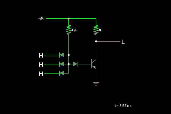
This is an NAND gate implemented using diode-transistor logic. Click on the inputs on the left to toggle their state. When all of the inputs are high, the output is low; otherwise, the output is high.
When all the inputs are high (3.6 V), the only path to ground through the 4.7k resistor is through the base of the transistor. So a base current flows. The transistor wants its collector-emitter current to be 100 times the base current. By attempting to bring the current up to this level, it brings the collector voltage down near ground.
When any of the inputs are low (at ground), the easiest path to ground through the 4.7k resistor is through the low input(s). This brings the bottom of the 4.7k resistor within one diode drop of ground. At this voltage, very little base current can flow to the right through both the diode and the base of the transistor. With no base current, the transistor is off, keeping the output high.