Theoretical Paper
- Computer Organization
- Data Structure
- Digital Electronics
- Object Oriented Programming
- Discrete Mathematics
- Graph Theory
- Operating Systems
- Software Engineering
- Computer Graphics
- Database Management System
- Operation Research
- Computer Networking
- Image Processing
- Internet Technologies
- Micro Processor
- E-Commerce & ERP
Practical Paper
Industrial Training
BCD Counter Circuit
A BCD counter is a special type of a digital counter which can count to ten on the application of a clock signal. We saw previously that toggle T-type flip flops can be used as individual divide-by-two counters. If we connect together several toggle flip-flops in a series chain we can produce a digital counter which stores or display the number of times a particular count sequence has occurred.
Clocked T-type flip-flops act as a binary divide-by-two counter and in asynchronous counters, the output of one counting stage provides the clock pulse for the next stage. Then a flip-flop counter has two possible output states and by adding more flip-flop stages, we can make a divide-by-2N counter. But the problem with 4-bit binary counters is that they count from 0000 to 1111. That is from 0 to 15 in decimal.
To make a digital counter which counts from 1 to 10, we need to have the counter count only the binary numbers 0000 to 1001. That is from 0 to 9 in decimal and fortunately for us, counting circuits are readily available as integrated circuits with one such circuit being the Asynchronous 74LS90 Decade Counter.
Digital counters count upwards from zero to some pre-determined count value on the application of a clock signal. Once the count value is reached, resetting them returns the counter back to zero to start again. A decade counter counts in a sequence of ten and then returns back to zero after the count of nine. Obviously to count up to a binary value of nine, the counter must have at least four flip-flops within its chain to represent each decimal digit as shown.
BCD Counter State Diagram

Then a decade counter has four flip-flops and 16 potential states, of which only 10 are used and if we connected a series of counters together we could counter to 100 or 1,000 or what ever number we wanted.
The total number of counts that a counter can count too is called its MODULUS. A counter that returns to zero after n counts is called a modulo-n counter, for example a modulo-8 (MOD-8), or modulo-16 (MOD-16) counter, etc, and for an “n-bit counter”, the full range of the count is from 0 to 2n-1.
But as we saw in the Asynchronous Counters tutorial, that a counter which resets after ten counts with a divide-by-10 count sequence from binary 0000 (decimal “0”) through to 1001 (decimal “9”) is called a binary-coded-decimal counter or BCD Counter for short and a MOD-10 counter can be constructed using a minimum of four toggle flip-flops.
It is called a BCD counter because its ten state sequence is that of a BCD code and does not have a regular pattern, unlike a straight binary counter. Then a single stage BCD counter such as the 74LS90 counts from decimal 0 to decimal 9 and is therefore capable of counting up to a maximum of nine pulses. Note also that a digital counter may count up or count down or count up and down (bidirectional) depending on an input control signal.
Binary-coded-decimal code is an 8421 code consisting of four binary digits. The 8421 designation refers to the binary weight of the four digits or bits used. For example, 23 = 8, 22 = 4, 21 = 2 and 20 = 1. The main advantage of BCD code is that it allows for the easy conversion between decimal and binary forms of numbers.
The 74LS90 BCD Counter
The 74LS90 integrated circuit is basically a MOD-10 decade counter that produces a BCD output code. The 74LS90 consists of four master-slave JK flip-flops internally connected to provide a MOD-2 (count-to-2) counter and a MOD-5 (count-to-5) counter. The 74LS90 has one independent toggle JK flip-flop driven by the CLK A input and three toggle JK flip-flops that form an asynchronous counter driven by the CLK B input as shown.
74LS90 BCD Counter
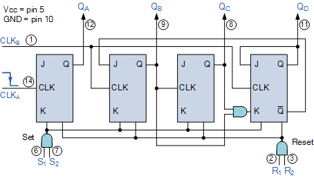
The counters four outputs are designated by the letter symbol Q with a numeric subscript equal to the binary weight of the corresponding bit in the BCD counters code. So for example, QA, QB, QC and QD. The 74LS90 counting sequence is triggered on the negative going edge of the clock signal, that is when the clock signal CLK goes from logic 1 (HIGH) to logic 0 (LOW).
The additional input pins R1 and R2 are counter “reset” pins while inputs S1 and S2 are “set” pins. When connected to logic 1, the Reset inputs R1 and R2 reset the counter back to zero, 0 (0000), and when the Set inputs S1 and S2 are connected to logic 1, they Set the counter to maximum, or 9 (1001) regardless of the actual count number or position.
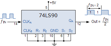
As we said before, the 74LS90 counter consists of a divide-by-2 counter and a divide-by-5 counter within the same package. Then we can use either counter to produce a divide-by-2 frequency counter only, a divide-by-5 frequency counter only or the two together to produce our desired divide-by-10 BCD counter.
With the four flip-flops making up the divide-by-5 counter section disabled, if a clock signal is applied to input pin 14 (CLKA) and the output taken from pin 12 (QA), we can produce a standard divide-by-2 binary counter for use in frequency dividing circuits as shown.
74LS90 Divide-by-2 Counter
To produce a standard divide-by-5 counter, we can disable the first flip-flop above, and apply the clock input signal directly to pin 1 (CLKB with the output signal being taken from pin 11 (QD) as shown.
74LS90 Divide-by-5 Counter
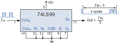
Note that with this divide-by-5 counter configuration, the output waveform is not symmetrical but has a 4:1 mark-space ratio. That is four input clock signals creates a LOW or logic “0” output and the fifth input clock signal produces a HIGH or logic “1” output.
To produce a divide-by-10 BCD decade counter, both internal counter circuits are used giving a 2 times 5 divide-by value. Since the first output QA from flip-flop A is not internally connected to the succeeding stages, the counter can be extended to form a 4-bit BCD counter by connecting this QA output to the CLKB input as shown
74LS90 Divide-by-10 Counter
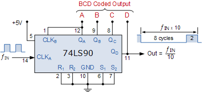
Then we can see that BCD counters are binary counters that count from 0000 to 1001 and then resets as it has the ability to clear all of its flip-flops after the ninth count. If we connect a pushbutton switch (SW1) to clock input CLKA, each time the pushbutton switch is released the counter will count by one. If we connected light emitting diodes (LED’s) to the output terminals, QA, QB, QC and QD as shown, we can view the binary coded decimal count as it takes place.
74LS90 BCD Decade Counter
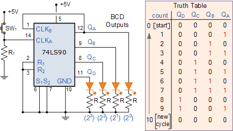
Successive applications of the pushbutton switch, SW1 will increase the count up to nine, 1001. At the tenth application the outputs ABCD will reset back to zero to start a new count sequence. With such a MOD-10 round number of pulses we can use the decade counter to drive a digital display.
If we want to display the count sequence using a seven-segment display, the BCD output needs to be decoded appropriately before it can be displayed. A digital circuit that can decode the four outputs of our 74LS90 BCD counter and light up the required segments of the display is called a Decoder.
Driving a Display
Fortunately for us, someone has already designed and developed a BCD to 7-segment Display Decoder IC such as the 74LS47 to do just that. The 74LS47 has four inputs for the BCD digits A, B, C and D and outputs for each of the segments of the seven-segment display. Note that a standard 7-segment LED display generally has 8 input connections, one for each LED segment and one that acts as a common terminal or connection for all the internal display segments. Some displays also have a decimal point (DP) option.
74LS47 BCD to 7-segment Driver
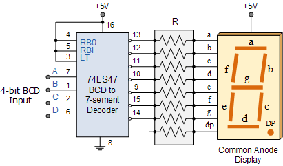
The 74LS47 display decoder receives the BCD code and generates the necessary signals to activate the appropriate LED segments responsible for displaying the number of pulses applied. As the 74LS47 decoder is designed for driving a common-anode display, a LOW (logic-0) output will illuminate an LED segment while a HIGH (logic-1) output will turn it “OFF”. For normal operation, the LT (Lamp test), BI/RBO (Blanking Input/Ripple Blanking Output) and RBI (Ripple Blanking Input) must all be open or connected to logic-1 (HIGH).
Note that while the 74LS47 has active LOW outputs and is designed to decode a common anode 7 segment LED display, the 74LS48 decoder/driver IC is exactly the same except that it has active HIGH outputs designed to decode a common cathode 7 segment display. So depending upon the type of 7-segment LED display you have you may need a 74LS47 or a 74LS48 decoder IC.
The 74LS47 binary coded decimal inputs can be connected to the corresponding outputs of the 74LS90 BCD Counter to display the count sequence on the 7-segment display as shown each time the pushbutton SW1 is pressed. By changing the position of the pushbutton and 10kΩ resistor, the count can be made to change on the activation or release of the pushbutton switch, SW1.
Final 4-bit BCD Counter Circuit
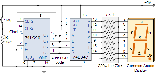
Note that a 7-segment display is made of seven individual light emitting diodes to form the display. The best method of limiting the current through a seven segment display is to use a current limiting resistor in series with each of the seven LED’s as shown. But we can do this in two ways.
Current Limiting Resistors
Single Resistor – here a single series current limiting resistor, R is used. If you are not particularly concerned with a constant display brightness, then this is the easiest and simplest option for controlling the 7-segment display.
The amount of light emitted by an LED varies with current through the device with the current flowing through the resistor being shared between the number of display segments. Then the brightness of the display now depends on how many segments are illuminated at the same time.
Multiple Resistors – here each segment has its own current limiting resistor as shown in our simple BCD counter circuit above.
Generally 7-segment displays require about 2 to 20 milli-amps to illuminate the segments, so the resistive value of the current limiting resistor (all will be identical) is chosen to limit the current to within these values. Note that some displays can be destroyed if driven at 40mA and above.
The advantage here is that the brightness of a particular LED segment does not depend on the state of the other six LED’s giving the display a constant brightness. The values of the current limiting resistors can be chosen to provide the correct amount of brightness as the amount of ambient light will also determine the required LED intensity.
Our circuit shows a simple 0 to 9 digital counter using a 74LS90 BCD Counter and a 74LS47 7-segment display driver. To count above 10 and produce a 2-digit base-ten counter and display, we would need to cascade two separate divide-by-ten counters together. A 2-digit BCD counter would count in decimal from 00 to 99 (0000 0000 to 1001 1001) and then reset back to 00. Note that although it will be a 2-digit counter, values representing Hexadecimal numbers from A through F are not valid in this code.
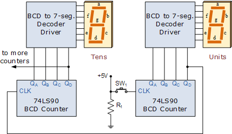
Likewise, if we wanted to count from 0 up to 999 (0000 0000 0000 to 1001 1001 1001), then three cascaded decade counters are required. In fact multiple decade counters can be constructed simply by cascading together individual BCD counters, one for each decade as shown.
2-digit BCD Counter from 00 to 99
BCD Counter Summary
In this tutorial we have seen that a BCD Counter is a devices that goes through a sequence of ten states when it is clocked and returns to 0 after the count of 9. In our simple example above, the input clock pulses are from a push button switch but counters can be used to count many real-world events such as counting moving objects.
However, suitable circuitry may be required to generate the electrical pulses for each event to be counted as these events may occur at discrete time intervals or they may be completely random.
In many digital electronic circuits and applications, digital counters are implemented using Toggle flip-flops or with any other type of flip-flop that can be connected to give the required switching function, or with the use of dedicated counting IC’s such as the 74LS90. Binary counters are counters that go through a binary sequence and an n-bit binary counter is made of “n” number of flip-flops counting from 0 to 2n-1.
BCD counters follow a sequence of ten states and count using BCD numbers from 0000 to 1001 and then returns to 0000 and repeats. Such a counter must have at least four flip-flops to represent each decimal digit, since a decimal digit is represented by a binary code with at least four bits giving a MOD-10 count.
We have also seen that the BCD coded output can be displayed using four LED’s or with a digital display. But to display each number from 0 to 9 requires a decoder circuit, which translates a binary coded number representation into the appropriate logic levels on each of the display segments.
Display decoder circuits can be constructed from combinational logic elements and there are many dedicated integrated circuits on the market to perform this function such as the 74LS47 BCD to 7-segment decoder/driver IC.
Most 7-segment displays are usually used in multi-digit counting applications so by cascading together more BCD counters, 4-digit counters giving displays with a maximum reading of 9999 can be constructed. The 74LS90 BCD Counter is a very flexible counting circuit and can be used as a frequency divider or made to divide any whole number count from 2 to 9 by feeding the appropriate outputs back to the IC’s Reset and Set inputs.

