Theoretical Paper
- Computer Organization
- Data Structure
- Digital Electronics
- Object Oriented Programming
- Discrete Mathematics
- Graph Theory
- Operating Systems
- Software Engineering
- Computer Graphics
- Database Management System
- Operation Research
- Computer Networking
- Image Processing
- Internet Technologies
- Micro Processor
- E-Commerce & ERP
Practical Paper
Industrial Training

Digital Comparator
Another common and very useful combinational logic circuit is that of the Digital Comparator circuit. Digital or Binary Comparators are made up from standard AND, NOR and NOT gates that compare the digital signals present at their input terminals and produce an output depending upon the condition of those inputs.
For example, along with being able to add and subtract binary numbers we need to be able to compare them and determine whether the value of input A is greater than, smaller than or equal to the value at input B etc. The digital comparator accomplishes this using several logic gates that operate on the principles of Boolean Algebra. There are two main types of Digital Comparator available and these are.
1. Identity Comparator – an Identity Comparator is a digital comparator that has only one output terminal for when A = B either “HIGH” A = B = 1 or “LOW” A = B = 0
2. Magnitude Comparator – a Magnitude Comparator is a type of digital comparator that has three output terminals, one each for equality, A = B greater than, A > B and less than A < B
The purpose of a Digital Comparator is to compare a set of variables or unknown numbers, for example A (A1, A2, A3, …. An, etc) against that of a constant or unknown value such as B (B1, B2, B3, …. Bn, etc) and produce an output condition or flag depending upon the result of the comparison. For example, a magnitude comparator of two 1-bits, (A and B) inputs would produce the following three output conditions when compared to each other.
A > B, A=B, A < B
Which means: A is greater than B, A is equal to B, and A is less than B
This is useful if we want to compare two variables and want to produce an output when any of the above three conditions are achieved. For example, produce an output from a counter when a certain count number is reached. Consider the simple 1-bit comparator below.
1-bit Digital Comparator
Then the operation of a 1-bit digital comparator is given in the following Truth Table.
Digital Comparator Truth Table
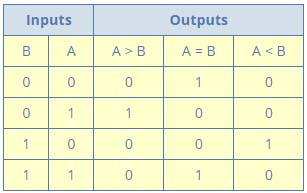
You may notice two distinct features about the comparator from the above truth table. Firstly, the circuit does not distinguish between either two “0” or two “1”‘s as an output A = B is produced when they are both equal, either A = B = “0” or A = B = “1”. Secondly, the output condition for A = B resembles that of a commonly available logic gate, the Exclusive-NOR or Ex-NOR function (equivalence) on each of the n-bits giving: Q = A ⊕ B
Digital comparators actually use Exclusive-NOR gates within their design for comparing their respective pairs of bits. When we are comparing two binary or BCD values or variables against each other, we are comparing the “magnitude” of these values, a logic “0” against a logic “1” which is where the term Magnitude Comparator comes from.
As well as comparing individual bits, we can design larger bit comparators by cascading together n of these and produce a n-bit comparator just as we did for the n-bit adder in the previous tutorial. Multi-bit comparators can be constructed to compare whole binary or BCD words to produce an output if one word is larger, equal to or less than the other.
A very good example of this is the 4-bit Magnitude Comparator. Here, two 4-bit words (“nibbles”) are compared to each other to produce the relevant output with one word connected to inputs A and the other to be compared against connected to input B as shown below.
4-bit Magnitude Comparator
Some commercially available digital comparators such as the TTL 74LS85 or CMOS 4063 4-bit magnitude comparator have additional input terminals that allow more individual comparators to be “cascaded” together to compare words larger than 4-bits with magnitude comparators of “n”-bits being produced. These cascading inputs are connected directly to the corresponding outputs of the previous comparator as shown to compare 8, 16 or even 32-bit words.
8-bit Word Comparator
When comparing large binary or BCD numbers like the example above, to save time the comparator starts by comparing the highest-order bit (MSB) first. If equality exists, A = B then it compares the next lowest bit and so on until it reaches the lowest-order bit, (LSB). If equality still exists then the two numbers are defined as being equal.
If inequality is found, either A > B or A < B the relationship between the two numbers is determined and the comparison between any additional lower order bits stops. Digital Comparator are used widely in Analogue-to-Digital converters, (ADC) and Arithmetic Logic Units, (ALU) to perform a variety of arithmetic operations.