Theoretical Paper
- Computer Organization
- Data Structure
- Digital Electronics
- Object Oriented Programming
- Discrete Mathematics
- Graph Theory
- Operating Systems
- Software Engineering
- Computer Graphics
- Database Management System
- Operation Research
- Computer Networking
- Image Processing
- Internet Technologies
- Micro Processor
- E-Commerce & ERP
Practical Paper
Industrial Training

Asynchronous Counter
In the previous tutorial we saw that an Asynchronous counter can have 2n-1 possible counting states e.g. MOD-16 for a 4-bit counter, (0-15) making it ideal for use in Frequency Division. But it is also possible to use the basic asynchronous counter to construct special counters with counting states less than their maximum output number.
This is achieved by forcing the counter to reset itself to zero at a pre-determined value producing a type of asynchronous counter that has truncated sequences. Then an n-bit counter that counts up to its maximum modulus ( 2n ) is called a full sequence counter and a n-bit counter whose modulus is less than the maximum possible is called a truncated counter.
But why would we want to create an asynchronous truncated counter that is not a MOD-4, MOD-8, or some other modulus that is equal to the power of two. The answer is that we can by using combinational logic to take advantage of the asynchronous inputs on the flip-flop. If we take the modulo-16 asynchronous counter and modified it with additional logic gates it can be made to give a decade (divide-by-10) counter output for use in standard decimal counting and arithmetic circuits.
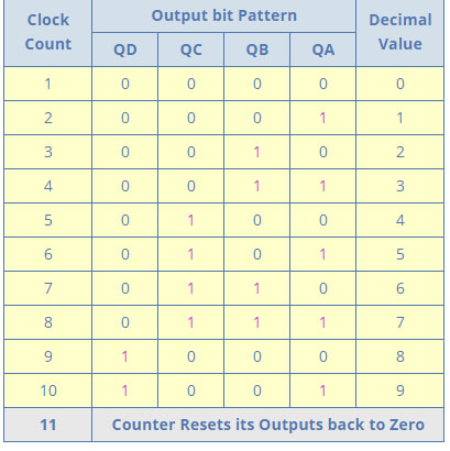
Such counters are generally referred to as Decade Counters. A decade counter requires resetting to zero when the output count reaches the decimal value of 10, ie. when DCBA = 1010 and to do this we need to feed this condition back to the reset input. A counter with a count sequence from binary “0000” (BCD = “0”) through to “1001” (BCD = “9”) is generally referred to as a BCD binary-coded-decimal counter because its ten state sequence is that of a BCD code but binary decade counters are more common.
Asynchronous Decade Counter
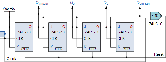
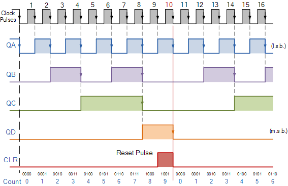
This type of asynchronous counter counts upwards on each trailing edge of the input clock signal starting from 0000 until it reaches an output 1001 (decimal 9). Both outputs QA and QD are now equal to logic “1”. One the application of the next clock pulse, the output from the 74LS10 NAND gate changes state from logic “1” to a logic “0” level.
As the output of the NAND gate is connected to the CLEAR ( CLR ) inputs of all the 74LS73 J-K Flip-flops, this signal causes all of the Q outputs to be reset back to binary 0000 on the count of 10. As outputs QA and QD are now both equal to logic “0” as the flip-flop’s have just been reset, the output of the NAND gate returns back to a logic level “1” and the counter restarts again from 0000. We now have a decade or Modulo-10 up-counter.
Decade Counter Truth Table
Decade Counter Timing Diagram
By using the same idea of truncating counter output sequences, the above circuit could easily be adapted to other counting cycles be simply changing the connections to the inputs of the NAND gate or by using other logic gate combinations.
So for example, a scale-of-twelve (modulo-12) can easily be made by simply taking the inputs to the NAND gate from the outputs at “QC” and “QD“, noting that the binary equivalent of 12 is 1100 and that output “QA” is the least significant bit (LSB).
Since the maximum modulus that can be implemented with n flip-flops is 2n, this means that when you are designing truncated asynchronous counters you should determine the lowest power of two that is greater than or equal to your desired modulus.
Lets say we wish to count from 0 to 39, or mod-40 and repeat. Then the highest number of flip-flops required would be six, n = 6 giving a maximum MOD of 64 as five flip-flops would not be enough as this only gives us a MOD-32.
Now suppose we wanted to build a “divide-by-128″ counter for frequency division we would need to cascade seven flip-flops since 128 = 27. Using dual flip-flops such as the 74LS74 we would still need four IC’s to complete the circuit.
One easy alternative method would be to use two TTL 7493’s as 4-bit ripple counter/dividers. Since 128 = 16 x 8, one 7493 could be configured as a “divide-by-16″ counter and the other as a “divide-by-8″ counter. The two IC’s would be cascaded together to form a “divide-by-128″ frequency divider as shown.
Of course standard IC asynchronous counters are available such as the TTL 74LS90 programmable ripple counter/divider which can be configured as a divide-by-2, divide-by-5 or any combination of both. The 74LS390 is a very flexible dual decade driver IC with a large number of “divide-by” combinations available ranging form divide-by-2, 4, 5, 10, 20, 25, 50, and 100.
Frequency Dividers
This ability of the ripple counter to truncate sequences to produce a “divide-by-n” output means that counters and especially ripple counters, can be used as frequency dividers to reduce a high clock frequency down to a more usable value for use in digital clocks and timing applications. For example, assume we require an accurate 1Hz timing signal to operate a digital clock.
We could quite easily produce a 1Hz square wave signal using a standard 555 timer chip configured as an Astable Multivibrator, but the manufacturers data sheet tells us that the 555 timer has a typical 1-2% timing error depending upon the manufacturer, and at low frequencies of 1Hz, this 2% timing error is not good.
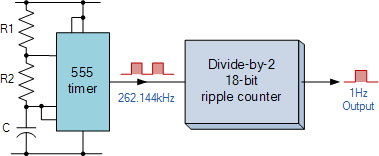
However, the data sheet also tells us that the maximum operating frequency of the 555 timer is about 300kHz and a 2% error at this high frequency, while still large at about 6kHz maximum, would be acceptable. So by choosing a higher timing frequency of say 262.144kHz and an 18-bit ripple (Modulo-18) counter we can easily make a precision 1Hz timing signal as shown below.
1Hz timing signal from a 18-bit asynchronous ripple counter.
This is of course a very simplistic example of how to produce accurate timing frequencies, but by using high frequency crystal oscillators and multi-bit frequency dividers, precision frequency generators can be produced for a full range of applications ranging from clocks or watches to event timing and even electronic piano/synthesizer or music type applications.
Unfortunately one of the main disadvantages with asynchronous counters is that there is a small delay between the arrival of the clock pulse at its input and it being present at its output due to the internal circuitry of the gate.
In asynchronous circuits this delay is called the Propagation Delay giving the asynchronous ripple counter the nickname of “propagation counter” and in some high frequency cases this delay can produce false output counts.
In large bit ripple counter circuits, if the delay of the separate stages are all added together to give a summed delay at the end of the counter chain the difference in time between the input signal and the counted output signal can be very large. This is why the Asynchronous Counter is generally not used in high frequency counting circuits were large numbers of bits are involved.
Also, the outputs from the counter do not have a fixed time relationship with each other and do not occur at the same instant in time due to their clocking sequence. In other words the output frequencies become available one by one, a sort of domino effect. Then, the more flip-flops that are added to an asynchronous counter chain the lower the maximum operating frequency becomes to ensure accurate counting. To overcome the problem of propagation delay Synchronous Counters were developed.
Then to summarise some of the advantages of Asynchronous Counters:
Asynchronous Counters can easily be made from Toggle or D-type flip-flops.
They are called “Asynchronous Counters” because the clock input of the flip-flops are not all driven by the same clock signal.
Each output in the chain depends on a change in state from the previous flip-flops output.
Asynchronous counters are sometimes called ripple counters because the data appears to “ripple” from the output of one flip-flop to the input of the next.
They can be implemented using “divide-by-n” counter circuits.
Truncated counters can produce any modulus number count.
Disadvantages of Asynchronous Counters:
An extra “re-synchronizing” output flip-flop may be required.
To count a truncated sequence not equal to 2n, extra feedback logic is required.
Counting a large number of bits, propagation delay by successive stages may become undesirably large.
This delay gives them the nickname of “Propagation Counters”.
Counting errors occur at high clocking frequencies.
Synchronous Counters are faster and more reliable as they use the same clock signal for all flip-flops.
In the next tutorial about Counters, we will look at the Synchronous Counter and see that the main characteristic of an synchronous counter is that the clock input of each flip-flop in the chain is connected to all of the flip-flops so that they are clocked simultaneously.