Theoretical Paper
- Computer Organization
- Data Structure
- Digital Electronics
- Object Oriented Programming
- Discrete Mathematics
- Graph Theory
- Operating Systems
- Software Engineering
- Computer Graphics
- Database Management System
- Operation Research
- Computer Networking
- Image Processing
- Internet Technologies
- Micro Processor
- E-Commerce & ERP
Practical Paper
Industrial Training

JPEG Baseline Compression page-5
JPEG Baseline Compression
Huffman AC Statistical Model Run-Length/Amplitude Combinations:
As can be seen from this figure there are two special codes defined, ZRL and EOB. EOB is the special case of their being no non-zero coefficient values in the current array. ZRL is the special case of there being 16 zeroes in sequence and there are more non-zero coefficient values in the remainder of the array. Again, as per the DC case, additional bits are required to complete the code for the RUN-SIZE symbol with the magnitude and sign information of the non-zero component of the symbol. Referring to the following figure gives the bits required
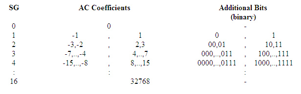
Additional bits for Huffman AC Coefficients coding [1]
Note that this is identical to the figure given for the additional bits in the DC coefficient section. The AC coefficients are processed from the first (or lowest order) AC coefficient in the zig-zag array through to the last coefficient (or 64th) value in the array. Obviously in practise, the array is scanned through until a non-zero value is found, or 16 zeroes in sequence are found.A typical run of codes being output from this procedure is one to three RUN-SIZE symbol codes and one EOB symbol code.
Note that the Huffman code tables for RUN-SIZE can be different depending on which component is currently being processed. If the JPEG standard libraries are being used then there is one each for luminance and chrominance components. The additional bits that get appended to the RUN-SIZE codes are always the same, irrespective of the component being processed.
Huffman Tree Construction:
The out put of the encoder consists of a sequence of three tokens, repeated until the block is completed.
Run Length: The number of consecutive zeros that preceded the current element the DCT output matrix.
Bit Count : The number of bits to follow in the amplitude number.
Amplitude : The amplitude of the DCT coefficient.
The coding sequence used here is a combination of Huffman codes and variable length integer coding. The run –length and bit-count values are combined to form Huffman code that is output . The bit count refers to the number of bits used to encode the amplitude as a variable –length integer.
The Huffman Algorithm
Huffman coding creates variable length codes that are an integral number of bits. Symbols with higher probabilities get shorter codes. Huffman codes have the unique prefix attribute, which of huffman codes can be correctly decoded despite being variable length. Decoding a stream of Huffman codes is generally done by following a binary decoder tree.
The procedure for building the tree is simple and elegant. The individual symbols are laid out as a string of leaf nodes that are going to be connected by a binary tree. Each node has a weight, which is simply the frequency of the symbol’s appearance. The tree is then built with the following steps.
Step 1: The two free nodes with the lowest wights are located.
Step 2: A parent node for these two is created. It is assigned a weight equal to the sum of the two child nodes.
Step 3: The parent node is added to the list of free nodes , and the two child nodes are removed from the list .
Step 4: One of the child nodes is designated as the path taken from the parent node when decoding a bit 0 . The other is arbitrarily set to the 1 bit.
Step 5: The previous steps are repeated until only one free node is left , this free node is designated the root node of the tree.
Example :
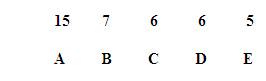
The five nodes are going to end up as the leaves of the decoding tree. When the process first starts , they make up the entire list of free nodes.
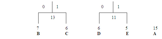
The first pass through the tree identifies the two free nodes with the lowest weights. D and E, with weights 6 and 5.( the tie between C and D does not effect the compression ratio). These two nodes are joined to a parent node , which is assigned a weight of 11. Nodes D and E are then removed from the free list.
Once this step is complete, we know what the least significant bits in the code for D and E are going to be D is assigned to the 0 branch of the parent node, and E is assigned to the 1 branch. These two bits will be the LSBs of the resulting codes.
On the next pass through the list of free nodes, the B and C nodes are picked as the two with the lowest weight. These are then attached to to a new parent node. The parent node is assigned a weight of 13, and B and C are removed from the free node list.
At this point the tree looks like
On the next pass, the two nodes with the lowest weights are the parent node s for the B/C and D/E pairs. These are tied together with a new parent node , which is assigned a weight of 24, and the children are removed from the free list . At this point we have assigned two bits each to the Huffman codes for B, C, D, and E, and we have yet to assign a single bit to the code for A.
Finally on the last pass , only two free nodes are left . The parent with a weight of 24 is tied with the A node to create a new parent with a weight of 39. After removing the two child nodes from the list , we are left with just one parent , meaning the tree is complete. The final result looks like,
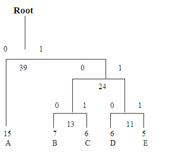
To determine the code for a given symbol, we have to walk from the leaf node to the root of the Huffman tree , accumulate new bits as we pass through each parent node. Unfortunately, the bits are returned to us in the reverse order that we want them, which means we have to push the bits onto a stack, then pop them off to generate the code.
The Huffman code table
Symbol |
Code |
A |
0 |
B |
100 |
C |
101 |
D |
110 |
E |
111 |
The symbol with the highest probability, A, has been assigned the fewest bits, and the symbol with the lowest probability, E, has assigned the most bits.