Theoretical Paper
- Computer Organization
- Data Structure
- Digital Electronics
- Object Oriented Programming
- Discrete Mathematics
- Graph Theory
- Operating Systems
- Software Engineering
- Computer Graphics
- Database Management System
- Operation Research
- Computer Networking
- Image Processing
- Internet Technologies
- Micro Processor
- E-Commerce & ERP
Practical Paper
Industrial Training

Arduino - Wireless Communication
The wireless transmitter and receiver modules work at 315 Mhz. They can easily fit into a breadboard and work well with microcontrollers to create a very simple wireless data link. With one pair of transmitter and receiver, the modules will only work communicating data one-way, however, you would need two pairs (of different frequencies) to act as a transmitter/receiver pair.
Note − These modules are indiscriminate and receive a fair amount of noise. Both the transmitter and receiver work at common frequencies and do not have IDs.
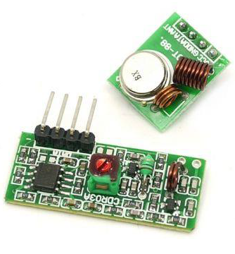
Receiver Module Specifications
-
Product Model − MX-05V
Operating voltage − DC5V
Quiescent Current − 4mA
Receiving frequency − 315Mhz
Receiver sensitivity − -105DB
Size − 30 * 14 * 7mm
Transmitter Module Specifications
-
Product Model − MX-FS-03V
Launch distance − 20-200 meters (different voltage, different results)
Operating voltage − 3.5-12V
Dimensions − 19 * 19mm
Operating mode − AM
Transfer rate − 4KB / S
Transmitting power − 10mW
Transmitting frequency − 315Mhz
An external antenna − 25cm ordinary multi-core or single-core line
Pinout from left → right − (DATA; VCC; GND)
Components Required
You will need the following components −
-
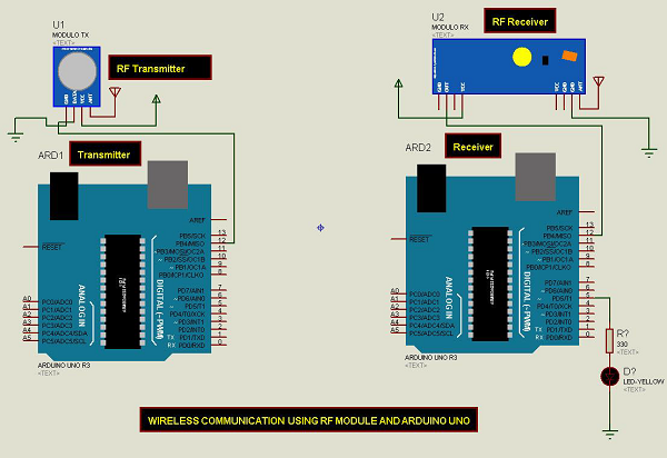
2 × Arduino UNO board
1 × Rf link transmitter
1 × Rf link receiver
Procedure
Follow the circuit diagram and make the connections as shown in the image given below.
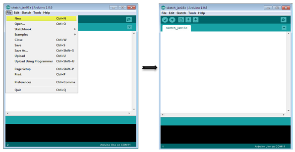
Sketch
Open the Arduino IDE software on your computer. Coding in the Arduino language will control your circuit. Open a new sketch File by clicking New.
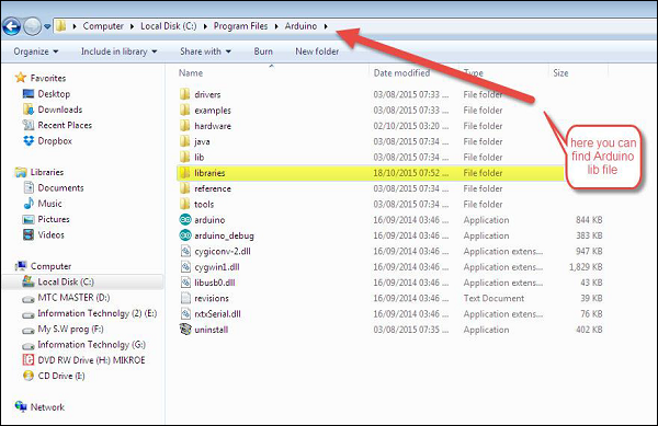
Note − You must include the keypad library in your Arduino library file. Copy and paste the VirtualWire.lib file in the libraries folder as highlighted in the screenshot given below.
Arduino Code for Transmitter
//simple Tx on pin D12
#include < VirtualWire.h>
char *controller;

void setup() {
   pinMode(13,OUTPUT);
   vw_set_ptt_inverted(true);
   vw_set_tx_pin(12);
   vw_setup(4000);// speed of data transfer Kbps
}

void loop() {
   controller="1" ;
   vw_send((uint8_t *)controller, strlen(controller));
   vw_wait_tx(); // Wait until the whole message is gone
   digitalWrite(13,1);
   delay(2000);
   controller="0" ;
   vw_send((uint8_t *)controller, strlen(controller));
   vw_wait_tx(); // Wait until the whole message is gone
   digitalWrite(13,0);
   delay(2000);
}
Code to Note
This is a simple code. First, it will send character '1' and after two seconds it will send character '0' and so on.
Arduino Code for Receiver
//simple Rx on pin D12
#include < VirtualWire.h>

void setup() {
   vw_set_ptt_inverted(true); // Required for DR3100
   vw_set_rx_pin(12);
   vw_setup(4000); // Bits per sec
   pinMode(5, OUTPUT);
   vw_rx_start(); // Start the receiver PLL running
}

void loop() {
   uint8_t buf[VW_MAX_MESSAGE_LEN];
   uint8_t buflen = VW_MAX_MESSAGE_LEN;
   if (vw_get_message(buf, &buflen)) // Non-blocking {
      if(buf[0]=='1') {
         digitalWrite(5,1);
      }
      if(buf[0]=='0') {
         digitalWrite(5,0);
      }
   }
}
Code to Note
The LED connected to pin number 5 on the Arduino board is turned ON when character '1' is received and turned OFF when character '0' received.