Theoretical Paper
- Computer Organization
- Data Structure
- Digital Electronics
- Object Oriented Programming
- Discrete Mathematics
- Graph Theory
- Operating Systems
- Software Engineering
- Computer Graphics
- Database Management System
- Operation Research
- Computer Networking
- Image Processing
- Internet Technologies
- Micro Processor
- E-Commerce & ERP
Practical Paper
Industrial Training

Arduino - DC Motor
In this chapter, we will interface different types of motors with the Arduino board (UNO) and show you how to connect the motor and drive it from your board.
There are three different type of motors −
-
DC motor
Servo motor
Stepper motor
A DC motor (Direct Current motor) is the most common type of motor. DC motors normally have just two leads, one positive and one negative. If you connect these two leads directly to a battery, the motor will rotate. If you switch the leads, the motor will rotate in the opposite direction.
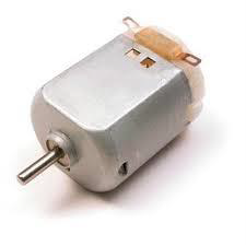
Warning − Do not drive the motor directly from Arduino board pins. This may damage the board. Use a driver Circuit or an IC.
We will divide this chapter into three parts −
-
Just make your motor spin
Control motor speed
Control the direction of the spin of DC motor
Components Required
You will need the following components −
-
1x Arduino UNO board
1x PN2222 Transistor
1x Small 6V DC Motor
1x 1N4001 diode
1x 270 Ω Resistor
Procedure
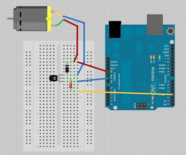
Follow the circuit diagram and make the connections as shown in the image given below.
Precautions
Take the following precautions while making the connections.
-
First, make sure that the transistor is connected in the right way. The flat side of the transistor should face the Arduino board as shown in the arrangement.
Second, the striped end of the diode should be towards the +5V power line according to the arrangement shown in the image.
Spin ControlArduino Code
int motorPin = 3;

void setup() {

}

void loop() {
   digitalWrite(motorPin, HIGH);
}
Code to Note
The transistor acts like a switch, controlling the power to the motor. Arduino pin 3 is used to turn the transistor on and off and is given the name 'motorPin' in the sketch.
Result
Motor will spin in full speed when the Arduino pin number 3 goes high.
Motor Speed Control
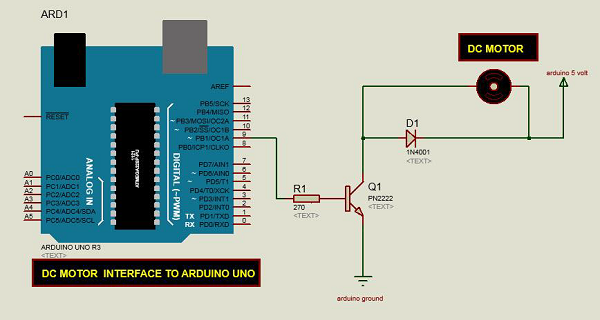
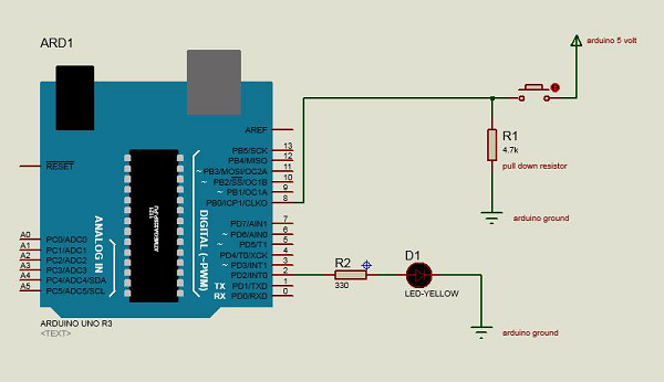
Following is the schematic diagram of a DC motor, connected to the Arduino board.
Arduino Code
int motorPin = 9;
void setup() {
pinMode(motorPin, OUTPUT);
Serial.begin(9600);
while (! Serial);
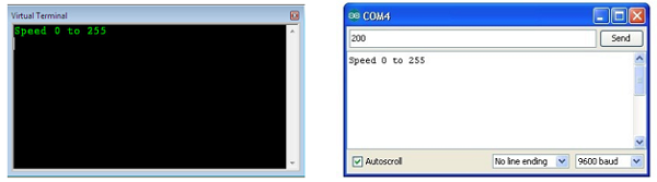
Serial.println("Speed 0 to 255");
}
void loop() {
if (Serial.available()) {
int speed = Serial.parseInt();
if (speed >= 0 && speed <= 255) {
analogWrite(motorPin, speed);
}
}
}
Code to Note
The transistor acts like a switch, controlling the power of the motor. Arduino pin 3 is used to turn the transistor on and off and is given the name 'motorPin' in the sketch.
When the program starts, it prompts you to give the values to control the speed of the motor. You need to enter a value between 0 and 255 in the Serial Monitor.
In the 'loop' function, the command 'Serial.parseInt' is used to read the number entered as text in the Serial Monitor and convert it into an 'int'. You can type any number here. The 'if' statement in the next line simply does an analog write with this number, if the number is between 0 and 255.
Result
The DC motor will spin with different speeds according to the value (0 to 250) received via the serial port.
Spin Direction Control
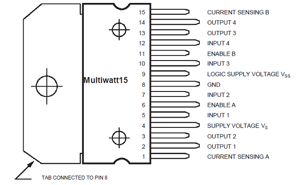
To control the direction of the spin of DC motor, without interchanging the leads, you can use a circuit called an H-Bridge. An H-bridge is an electronic circuit that can drive the motor in both directions. H-bridges are used in many different applications. One of the most common application is to control motors in robots. It is called an H-bridge because it uses four transistors connected in such a way that the schematic diagram looks like an "H."
We will be using the L298 H-Bridge IC here. The L298 can control the speed and direction of DC motors and stepper motors, and can control two motors simultaneously. Its current rating is 2A for each motor. At these currents, however, you will need to use heat sinks.
Components Required
You will need the following components −
-
1 × L298 bridge IC
1 × DC motor
1 × Arduino UNO
1 × breadboard
10 × jumper wires
Procedure
Following is the schematic diagram of the DC motor interface to Arduino Uno board.
The above diagram shows how to connect the L298 IC to control two motors. There are three input pins for each motor, Input1 (IN1), Input2 (IN2), and Enable1 (EN1) for Motor1 and Input3, Input4, and Enable2 for Motor2.
Since we will be controlling only one motor in this example, we will connect the Arduino to IN1 (pin 5), IN2 (pin 7), and Enable1 (pin 6) of the L298 IC. Pins 5 and 7 are digital, i.e. ON or OFF inputs, while pin 6 needs a pulse-width modulated (PWM) signal to control the motor speed.
The following table shows which direction the motor will turn based on the digital values of IN1 and IN2.
| IN1 | IN2 | Motor Behavior |
| BRAKE | ||
| 1 | FORWARD | |
| 1 | BACKWARD | |
| 1 | 1 | BRAKE |
Pin IN1 of the IC L298 is connected to pin 8 of Arduino while IN2 is connected to pin 9. These two digital pins of Arduino control the direction of the motor. The EN A pin of IC is connected to the PWM pin 2 of Arduino. This will control the speed of the motor.
To set the values of Arduino pins 8 and 9, we have used the digitalWrite() function, and to set the value of pin 2, we have to use the analogWrite() function.
Connection Steps
-
Connect 5V and the ground of the IC to 5V and the ground of Arduino, respectively.
Connect the motor to pins 2 and 3 of the IC.
Connect IN1 of the IC to pin 8 of Arduino.
Connect IN2 of the IC to pin 9 of Arduino.
Connect EN1 of IC to pin 2 of Arduino.
Connect SENS A pin of IC to the ground.
Connect Arduino using Arduino USB cable and upload the program to Arduino using Arduino IDE software.
Provide power to Arduino board using power supply, battery, or USB cable.
Arduino Code
const int pwm = 2 ; //initializing pin 2 as pwm
const int in_1 = 8 ;
const int in_2 = 9 ;
//For providing logic to L298 IC to choose the direction of the DC motor

void setup() {
   pinMode(pwm,OUTPUT) ; //we have to set PWM pin as output
   pinMode(in_1,OUTPUT) ; //Logic pins are also set as output
   pinMode(in_2,OUTPUT) ;
}

void loop() {
   //For Clock wise motion , in_1 = High , in_2 = Low
   digitalWrite(in_1,HIGH) ;
   digitalWrite(in_2,LOW) ;
   analogWrite(pwm,255) ;
   /* setting pwm of the motor to 255 we can change the speed of rotation
   by changing pwm input but we are only using arduino so we are using highest
   value to driver the motor */
   //Clockwise for 3 secs
   delay(3000) ;
   //For brake
   digitalWrite(in_1,HIGH) ;
   digitalWrite(in_2,HIGH) ;
   delay(1000) ;
   //For Anti Clock-wise motion - IN_1 = LOW , IN_2 = HIGH
   digitalWrite(in_1,LOW) ;
   digitalWrite(in_2,HIGH) ;
   delay(3000) ;
   //For brake
   digitalWrite(in_1,HIGH) ;
   digitalWrite(in_2,HIGH) ;
   delay(1000) ;
}
Result
The motor will run first in the clockwise (CW) direction for 3 seconds and then counter-clockwise (CCW) for 3 seconds.