Theoretical Paper
- Computer Organization
- Data Structure
- Digital Electronics
- Object Oriented Programming
- Discrete Mathematics
- Graph Theory
- Operating Systems
- Software Engineering
- Computer Graphics
- Database Management System
- Operation Research
- Computer Networking
- Image Processing
- Internet Technologies
- Micro Processor
- E-Commerce & ERP
Practical Paper
Industrial Training

Projection
taking 2d objects and mapping onto a 2d screen is pretty straightforward. the window is the same plane as the 2d world. now we are taking 3d objects and mapping them onto a 2d screen.
here is where the advantage of separating the model world from its rendered image becomes more obvious. the easiest way to think about converting 3d world into 2d image is the way we do it in real life - with a camera.
lets say we have an object in the real world (e.g. the sears tower.) the tower sits there in its 3dness. you can move around the tower, on the ground, on the water, in the air, and take pictures of it, converting it to a 2d image. depending on where you put the camera and the settings on the camera, and other factors such as light levels, you get different looking images.
in the computer we have a synthetic camera taking still or moving pictures of a synthetic environment. while this synthetic camera gives you a much wider range of options than a real camera, you will find it is very easy to take a picture of nothing at all.
and a quick trip to the renaissance ...
albrecht dürer, daraughsman drawing a recumbent woman (1525) woodcut illusion from 'the teaching of measurements.'
projections
projection is 'formed' on the view plane (planar geometric projection)
rays (projectors) projected from the center of projection pass through each point of the models and intersect projection plane.
since everything is synthetic, the projection plane can be in front of the models, inside the models, or behind the models.
2 main types: perspective projection and parallel projection.
- center of projection infinitely far from view plane
- projectors will be parallel to each other
- need to define the direction of projection (vector)
- 2 sub-types
- orthographic - direction of projection is normal to view plane
- oblique - direction of projection not normal to view plane
- better for drafting / cad applications
- center of projection finitely far from view plane
- projectors will not be parallel to each other
- need to define the location of the center of projection (point)
- classified into 1, 2, or 3-point perspective
- more visually realistic - has perspective foreshortening (objects further away appear smaller)
parallel :
perspective :
which type of projection is used depends on the needs of the user - whether the goal is the mathematically correct depiction of length and angles, or a realistic looking image of the object.
specifying a 3d view
danger, watch out for acronyms being tossed out!
need to know the type of projection
need to know the clipping volume
in opengl there are the following functions:
glfrustum(left, right, bottom, top, near, far);
glortho(left, right, bottom, top, near, far);
view plane defined by:
- point on the plane - view reference point (vrp)
- normal to the plane pointing towards the center of projection- view-plane normal (vpn)
view plane can be anywhere in the world-space
the center of projection represents the location of the viewer's eye or the camera's lens.
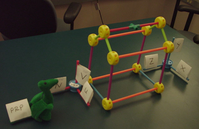
need to define a 3d viewing reference coordinate system
(vrc) which has axis u, v, n
- origin of vrc is the vrp
- n axis of vrc is the vpn
- v axis of vrc is called the view-up vector (vup)
- u axis of vrc is defined to form a right-hand coordinate system with n and v
since the view plane (n=0) is infinite (as it is a plane) we need to declare a region of that plane to be our window.
- (umin, vmin) to (umax, vmax)
- center of window (cw) on view plane does not have to be vrp
- vrp may not even be within the window
projection reference point (prp) defines the center of projection and direction of projection (dop)
- prp given in vrc coordinate system (that is, its position is given relative to the vrp)
- parallel projection - dop is from prp to cw, and all projectors are parallel.
- perspective projection - center of projection is the prp
n-point perspective
perspective projections are categorized by the number of axes the view plane cuts (ie 1-point perspective, 2-point perspective or 3-point perspective)
if the plane cuts the z axis only, then lines parallel to the z axis will meet at infinity; lines parallel to the x or y axis will not meet at infinity because they are parallel to the view plane. this is 1-point perspective.
if the plane cuts the x and z axes, then lines parallel to the x axis or the z axis will meet at infinity; lines parallel to the y axis will not meet at infinity because they are parallel to the view plane. this is 2-point perspective.
if the plane cuts the x, y, and z axis then lines parallel to the x, y, or z axis will meet at infinity. this is 3-point perspective.
the n-point perspectives can work with any combination of the x, y, z axis.
view volumes
the view volume in orthographic projection:
the view volume in perspective projection:
the front plane's location is given by the front distance f
relative to the vrp
the back plane's location is given by the back distance b relative
to the vrp
in both cases the positive direction is in the direction of the
vpn
viewing volume has 6 clipping planes (left, right, top, bottom,
near (hither), far (yon)) instead of the 4 clipping lines we had
in the 2d case, so clipping is a bit more complicated
perspective - viewing volume is a frustum of a 4-sided pyramid
parallel - viewing volume is a rectangular parallelepiped (ie
a box)
parallel examples
in the red version of the foley vandam book see p.211-212.
in the white version of the foley vandam book see p.250-252.
perspective examples
here are some examples using the same house as in the book (figure 6.18 in the red version of the foley vandam book, figure 6.24 in the white version of the foley vandam book, but using andy johnson's solution to the former hw3 as the viewing program:
the object is a house with vertices:
 0, 0,30
	16, 0,30
	16,10,30
	8,16,30
	0,10,30
	0, 0,54
	16, 0,54
	16,10,54
	8,16,54
	0,10,54
vrp= 0 0 54 or vrp= 8 7 54
	vpn= 0 0 1 vpn= 0 0 1
	vup= 0 1 0 vup= 0 1 0
	prp= 8 7 30 prp= 0 0 30

	u: -1 to 17 u: -9 to 9
	v: -2 to 16 v: -9 to 9
vrp= 16 0 54
	vpn= 1 0 0
	vup= 0 1 0
	prp= 12 8 16

	u: -1 to 25
	v: -5 to 21
vrp= 16 0 54
	vpn= 1 0 1
	vup= 0 1 0
	prp= 6 8 10

	u: -22 to 22
	v: -2 to 18
for other examples, in the red version of the foley vandambook
see p.206-211.
in the white version of the foley vandam book see p.245-250.
example with a finite view volume
in the red version of the foley vandam book see p.212-213.
in the white version of the foley vandam book see p.253.
now, how do we actually implement this?!?!?!?
with lots and lots of matrices.
method 1:
- extend 3d coordinates to homogeneous coordinates
- normalize the homogeneous coordinates
- go back to 3d coordinates
- clip
- extend 3d coordinates to homogeneous coordinates
- perform projection
- translate and scale into device coordinates
- go to 2d coordinates
method 2:
- extend 3d coordinates to homogeneous coordinates
- normalize the homogeneous coordinates
- clip
- translate and scale into device coordinates
- go to 2d coordinates