Theoretical Paper
- Computer Organization
- Data Structure
- Digital Electronics
- Object Oriented Programming
- Discrete Mathematics
- Graph Theory
- Operating Systems
- Software Engineering
- Computer Graphics
- Database Management System
- Operation Research
- Computer Networking
- Image Processing
- Internet Technologies
- Micro Processor
- E-Commerce & ERP
Practical Paper
Industrial Training

Methods of Interrupts
There are two main types of interrupt in the 8086 microprocessor, internal and external hardware interrupts. Hardware interrupts occur when a peripheral device asserts an interrupt input pin of the microprocessor. Whereas internal interrupts are initiated by the state of the CPU (e.g. divide by zero error) or by an instruction.
Provided the interrupt is permitted, it will be acknowledged by the processor at the end of the current memory cycle. The processor then services the interrupt by branching to a special service routine written to handle that particular interrupt. Upon servicing the device, the processor is then instructed to continue with what is was doing previously by use of the "return from interrupt" instruction.
The status of the programme being executed must first be saved. The processors registers will be saved on the stack, or, at very least, the programme counter will be saved. Preserving those registers which are not saved will be the responsibility of the interrupt service routine. Once the programme counter has been saved, the processor will branch to the address of the service routine.
Edge or Level sensitive Interrupts
Edge level interrupts are recognised on the falling or rising edge of the input signal. They are generally used for high priority interrupts and are latched internally inside the processor. If this latching was not done, the processor could easily miss the falling edge (due to its short duration) and thus not respond to the interrupt request.
Level sensitive interrupts overcome the problem of latching, in that the requesting device holds the interrupt line at a specified logic state (normally logic zero) till the processor acknowledges the interrupt. This type of interrupt can be shared by other devices in a wired 'OR' configuration, which is commonly used to support daisy chaining and other techniques.
Maskable Interrupts
The processor can inhibit certain types of interrupts by use of a special interrupt mask bit. This mask bit is part of the flags/condition code register, or a special interrupt register. In the 8086 microprocessor if this bit is clear, and an interrupt request occurs on the Interrupt Request input, it is ignored.
Non-Maskable Interrupts
There are some interrupts which cannot be masked out or ignored by the processor. These are associated with high priority tasks which cannot be ignored (like memory parity or bus faults). In general, most processors support the Non-Maskable Interrupt (NMI). This interrupt has absolute priority, and when it occurs, the processor will finish the current memory cycle, then branch to a special routine written to handle the interrupt request.
Advantages of Interrupts
Interrupts are used to ensure adequate service response times by the processing. Sometimes, with software polling routines, service times by the processor cannot be guaranteed, and data may be lost. The use of interrupts guarantees that the processor will service the request within a specified time period, reducing the likelihood of lost data.
Interrupt Latency
The time interval from when the interrupt is first asserted to the time the CPU recognises it. This will depend much upon whether interrupts are disabled, prioritized and what the processor is currently executing. At times, a processor might ignore requests whilst executing some indivisible instruction stream (read-write-modify cycle). The figure that matters most is the longest possible interrupt latency time.
Interrupt Response Time
The time interval between the CPU recognising the interrupt to the time when the first instruction of the interrupt service routine is executed. This is determined by the processor architecture and clock speed.
![]()
The Operation of an Interrupt sequence on the 8086 Microprocessor:
1. External interface sends an interrupt signal, to the Interrupt Request (INTR) pin, or an internal interrupt occurs.
2. The CPU finishes the present instruction (for a hardware interrupt) and sends Interrupt Acknowledge (INTA) to hardware interface.
3. The interrupt type N is sent to the Central Processor Unit (CPU) via the Data bus from the hardware interface.
4. The contents of the flag registers are pushed onto the stack.
5. Both the interrupt (IF) and (TF) flags are cleared. This disables the INTR pin and the trap or single-step feature.
6. The contents of the code segment register (CS) are pushed onto the Stack.
7. The contents of the instruction pointer (IP) are pushed onto the Stack.
8. The interrupt vector contents are fetched, from (4 x N) and then placed into the IP and from (4 x N +2) into the CS so that the next instruction executes at the interrupt service procedure addressed by the interrupt vector.
9. While returning from the interrupt-service routine by the Interrupt Return (IRET) instruction, the IP, CS and Flag registers are popped from the Stack and return to their state prior to the interrupt.
![]()
Multiple Interrupts
If more than one device is connected to the interrupt line, the processor needs to know to which device service routine it should branch to. The identification of the device requesting service can be done in either hardware or software, or a combination of both. The three main methods are:
-
Software Polling,
-
Hardware Polling, (Daisy Chain),
-
Hardware Identification (Vectored Interrupts).
Software Polling Determination of the Requesting Device
A software routine is used to identify the device requesting service. A simple polling technique is used, each device is checked to see if it was the one needing service.

Having identified the device, the processor then branches to the appropriate interrupt-handling-routine address for the given device. The order in which the devices appear in the polling sequence determines their priority.
Summary of Software Polled I/O
Polling is the most common and simplest method of I/O control. It requires no special hardware and all I/O transfers are controlled by the CPU programme. Polling is a synchronous mechanism, by which devices are serviced in sequential order.
The polling technique, however, has limitations.
1) it is wasteful of the processors time, as it needlessly checks the status of all devices all the time,
2) it is inherently slow, as it checks the status of all I/O devices before it comes back to check any given one again,
3) when fast devices are connected to a system, polling may simply not be fast enough to satisfy the minimum service requirements,
4) priority of the device is determined by the order in the polling loop, but it is possible to change it via software.
Software/Hardware Driven Identification (Daisy Chain)
This is significantly faster than a pure software approach. A daisy chain is used to identify the device requesting service.
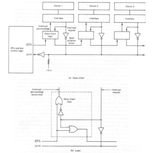
Daisy Chain Polling Arangement
Daisy chaining is used for level sensitive interrupts, which act like a wired 'OR' gate. Any requesting device can take the interrupt line low, and keep it asserted low until it is serviced.
Because more than one device can assert the shared interrupt line simultaneously, some method must be employed to ensure device priority. This is done using the interrupt acknowledge signal generated by the processor in response to an interrupt request.
Each device is connected to the same interrupt request line, but the interrupt acknowledge line is passed through each device, from the highest priority device first, to the lowest priority device last.
After preserving the required registers, the microprocessor generates an interrupt acknowledge signal. This is gated through each device. If device 1 generated the interrupt, it will place its identification signal on the data bus, which is read by the processor, and used to generate the address of the interrupt-service routine. If device 1 did not request the servicing, it will pass the interrupt acknowledge signal on to the next device in the chain. Device 2 follows the same procedure, and so on.
Hardware Identification (Vectored Interrupts)
This is the fastest system. The onus is placed on the requesting device to request the interrupt, and identify itself. The identity could be a branching address for the desired interrupt-handling routine.
If the device just supplies an identification number, this can be used in conjunction with a lookup table to determine the address of the required service routine. Response time is best when the device requesting service also supplies a branching address.
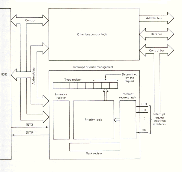
Priority Interrupt Management Controller
Priority Interrupt Controller Chips (PIC's) are hardware chips designed to make the task of a device presenting its own address to the CPU simple. The PIC also assesses the priority of the devices connected to it. Modern PIC's can also be programmed to prevent the generation of interrupts which are lower than a desired level.
The decoded location is connected to the output of a priority encoder. The input of the priority encoder is connected to each device. When a device requests service, the priority encoder presents a special code combination (unique for each device) to the decoded memory location. The port thus holds the value or address associated with the highest device requesting service.
The priority encoder arranges all devices in a list, devices given a lower priority are serviced when no other higher priority devices need servicing. This simplifies the software required to determine the device, resulting in an increase in speed.
The disadvantages are:
1) the extra chip required,
2) resultant increases in cost,
3) more board space and power consumption,
4) fixed priority in hardware.