Theoretical Paper
- Computer Organization
- Data Structure
- Digital Electronics
- Object Oriented Programming
- Discrete Mathematics
- Graph Theory
- Operating Systems
- Software Engineering
- Computer Graphics
- Database Management System
- Operation Research
- Computer Networking
- Image Processing
- Internet Technologies
- Micro Processor
- E-Commerce & ERP
Practical Paper
Industrial Training

Types of Buses in Computer Architecture
Computers comprises of many internal components and in order for these components to communicate with each other, a ‘bus’ is used for that purpose.
A bus is a common pathway through which information flows from one component to another. This pathway is used for communication purpose and can be established between two or more computer components. We are going to review different computer bus architectures that are used in computers.
Functions of Buses in Computers
The functions of buses can be summarized as below:
1. Data sharing - All types of buses found on a computer must be able to transfer data between the computer peripherals connected to it.
The data is transferred in in either serial or parallel, which allows the exchange of 1, 2, 4 or even 8 bytes of data at a time. (A byte is a group of 8 bits). Buses are classified depending on how many bits they can move at the same time, which means that we have 8-bit, 16-bit, 32-bit or even 64-bit buses.
2. Addressing - A bus has address lines, which match those of the processor. This allows data to be sent to or from specific memory locations.
3. Power - A bus supplies power to various peripherals that are connected to it.
4. Timing - The bus provides a system clock signal to synchronize the peripherals attached to it with the rest of the system.
The expansion bus facilitates the easy connection of additional components and devices on a computer for example the addition of a TV card or sound card.
Bus Terminologies
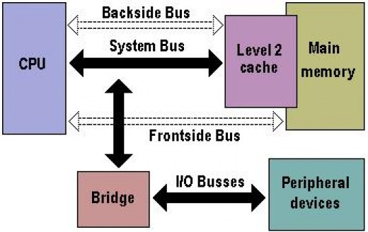
Computers can be viewed to be having just two types of buses:
1. System bus:- The bus that connects the CPU to main memory on the motherboard. The system bus is also called the front-side bus, memory bus, local bus, or host bus.
2. A number of I/O Buses, (Acronym for input/output), connecting various peripheral devices to the CPU -these are connected to the system bus via a ‘bridge’ implemented in the processors chipset. Other names for the I/O bus include “expansion bus", "external bus” or “host bus”.
Expansion Bus Types
These are some of the common expansion bus types that have ever been used in computers:
ISA - Industry Standard Architecture
EISA - Extended Industry Standard Architecture
MCA - Micro Channel Architecture
VESA - Video Electronics Standards Association
PCI - Peripheral Component Interconnect
PCMCIA - Personal Computer Memory Card Industry Association (Also called PC bus)
AGP - Accelerated Graphics Port
SCSI - Small Computer Systems Interface.
| 8-Bit ISA card (XT-Bus) | 16-Bit ISA (AT –Bus card) |
|---|---|
| 8-bit data interface | 16-bit data interface |
| 4.77 MHZ bus | 8-MHZ bus |
| 62-pin connector | 62-pin connector |
| 36-pin AT extension connection |
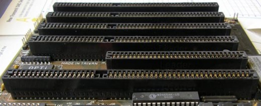
ISA Bus
This is the most common type of early expansion bus, which was designed for use in the original IBM PC.The IBM PC-XT used an 8-bit bus design. This means that the data transfers take place in 8 bit chunks (i.e. one byte at a time) across the bus. The ISA bus ran at a clock speed of 4.77 MHz.
For the 80286-based IBM PC-AT, an improved bus design, which could transfer 16-bits of data at a time, was announced. The 16-bit version of the ISA bus is sometimes known as the AT bus. (AT-Advanced Technology)
The improved AT bus also provided a total of 24 address lines, which allowed 16MB of memory to be addressed. The AT bus was backward compatible with its 8-bit predecessor and allowed 8-bit cards to be used in 16-bit expansion slots.
When it first appeared the 8-bit ISA bus ran at a speed of 4.77MHZ – the same speed as the processor. It was improved over the years and eventually the AT bus ran at a clock speed of 8MHz.
MCA (Micro Channel Architecture)
This bus was developed by IBM as a replacement for ISA when they designed the PS/2 PC which was launched in 1987.
The bus offered a number of technical improvements over the ISA bus. For instance, the MCA runs at a faster speed of 10MHz and can support either 16-bit or 32-bit data. It also supports bus mastering - a technology that placed a mini-processor on each expansion card. These mini-processors controlled much of the data transfer allowing the CPU to perform other tasks.
One advantage of MCA was that the plug-in cards were software configurable i.e. they required minimal intervention by the user when configuring.
The MCA expansion bus did not support ISA cards and IBM decided to charge other manufacturers royalties for use of the technology. This made it unpopular and it is now an obsolete technology.
EISA (Extended Industry Standard Architecture)
It was developed by a group of manufactures as an alternative to MCA. It was designed to use a 32-bit data path and provided 32 address lines giving access to 4GB of memory.
Like the MCA, EISA offered a disk-based setup for the cards, but it still ran at 8MHz in order for it to be compatible with ISA.
The EISA expansion slots are twice as deep as an ISA slot. If an ISA card is placed in an EISA slot it will use only the top row of connectors, whereas a full EISA card uses both rows. It offered bus mastering.
EISA cards were relatively expensive and were normally found on high-end workstations and network servers.
VESA Bus
Also known as the Local bus or the VESA-Local bus. VESA (Video Electronics Standards Association) was invented to help standardize PCs video specifications, thus solving the problem of proprietary technology where different manufacturers were attempting to develop their own buses.
The VL Bus provides 32-bit data path and can run at 25 or 33MHZ. It ran at the same clock frequency as the host CPU. But this became a problem as processor speeds increased because, the faster the peripherals are required to run, the more expensive they are to manufacture.
It was difficult to implement the VL-Bus on newer chips such as the 486s and the new Pentiums and so eventually the VL-Bus was superseded by PCI.
VESA slots have extra set of connectors and therefore the cards are larger. The VESA design was backward compatible with the older ISA cards.