Theoretical Paper
- Computer Organization
- Data Structure
- Digital Electronics
- Object Oriented Programming
- Discrete Mathematics
- Graph Theory
- Operating Systems
- Software Engineering
- Computer Graphics
- Database Management System
- Operation Research
- Computer Networking
- Image Processing
- Internet Technologies
- Micro Processor
- E-Commerce & ERP
Practical Paper
Industrial Training
Protocol and standards
Data-link layer is responsible for implementation of point-to-point flow and error control mechanism.
Flow Control
When a data frame (Layer-2 data) is sent from one host to another over a single medium, it is required that the sender and receiver should work at the same speed. That is, sender sends at a speed on which the receiver can process and accept the data. What if the speed (hardware/software) of the sender or receiver differs? If sender is sending too fast the receiver may be overloaded, (swamped) and data may be lost.
Two types of mechanisms can be deployed to control the flow:
Stop and Wait
This flow control mechanism forces the sender after transmitting a data frame to stop and wait until the acknowledgement of the data-frame sent is received.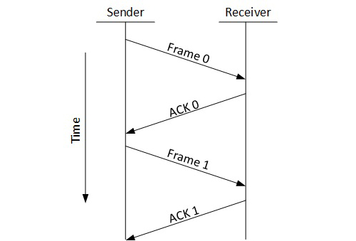
Sliding Window
In this flow control mechanism, both sender and receiver agree on the number of data-frames after which the acknowledgement should be sent. As we learnt, stop and wait flow control mechanism wastes resources, this protocol tries to make use of underlying resources as much as possible.
Error Control
When data-frame is transmitted, there is a probability that data-frame may be lost in the transit or it is received corrupted. In both cases, the receiver does not receive the correct data-frame and sender does not know anything about any loss.In such case, both sender and receiver are equipped with some protocols which helps them to detect transit errors such as loss of data-frame. Hence, either the sender retransmits the data-frame or the receiver may request to resend the previous data-frame.
Requirements for error control mechanism:
Error detection - The sender and receiver, either both or any, must ascertain that there is some error in the transit.
Positive ACK - When the receiver receives a correct frame, it should acknowledge it.
Negative ACK - When the receiver receives a damaged frame or a duplicate frame, it sends a NACK back to the sender and the sender must retransmit the correct frame.
Retransmission: The sender maintains a clock and sets a timeout period. If an acknowledgement of a data-frame previously transmitted does not arrive before the timeout the sender retransmits the frame, thinking that the frame or it’s acknowledgement is lost in transit.
There are three types of techniques available which Data-link layer may deploy to control the errors by Automatic Repeat Requests (ARQ):
Stop-and-wait ARQ
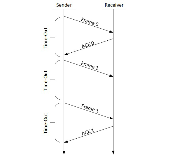
The following transition may occur in Stop-and-Wait ARQ:
- The sender maintains a timeout counter.
- When a frame is sent, the sender starts the timeout counter.
- If acknowledgement of frame comes in time, the sender transmits the next frame in queue.
- If acknowledgement does not come in time, the sender assumes that either the frame or its acknowledgement is lost in transit. Sender retransmits the frame and starts the timeout counter.
- If a negative acknowledgement is received, the sender retransmits the frame.
Go-Back-N ARQ
Stop and wait ARQ mechanism does not utilize the resources at their best.When the acknowledgement is received, the sender sits idle and does nothing. In Go-Back-N ARQ method, both sender and receiver maintain a window.
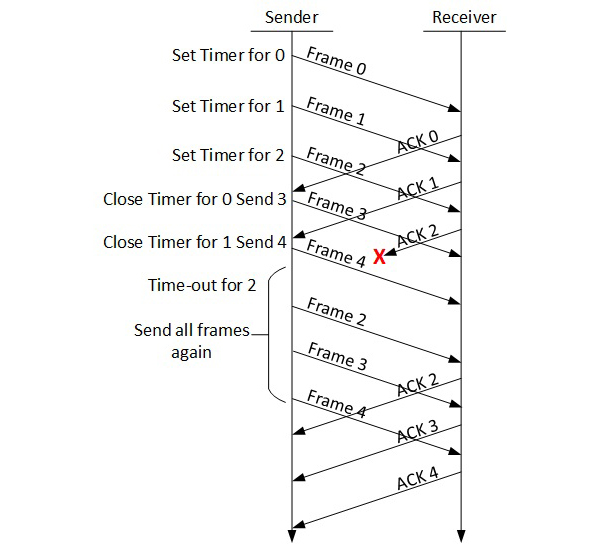
The sending-window size enables the sender to send multiple frames without receiving the acknowledgement of the previous ones. The receiving-window enables the receiver to receive multiple frames and acknowledge them. The receiver keeps track of incoming frame’s sequence number.
When the sender sends all the frames in window, it checks up to what sequence number it has received positive acknowledgement. If all frames are positively acknowledged, the sender sends next set of frames. If sender finds that it has received NACK or has not receive any ACK for a particular frame, it retransmits all the frames after which it does not receive any positive ACK.
Selective Repeat ARQ
In Go-back-N ARQ, it is assumed that the receiver does not have any buffer space for its window size and has to process each frame as it comes. This enforces the sender to retransmit all the frames which are not acknowledged.
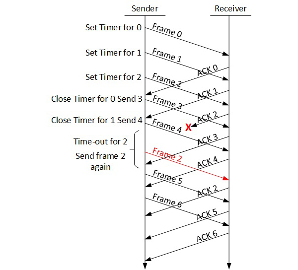
In Selective-Repeat ARQ, the receiver while keeping track of sequence numbers, buffers the frames in memory and sends NACK for only frame which is missing or damaged.
The sender in this case, sends only packet for which NACK is received.
Every computer in a network has an IP address by which it can be uniquely identified and addressed. An IP address is Layer-3 (Network Layer) logical address. This address may change every time a computer restarts. A computer can have one IP at one instance of time and another IP at some different time.
Address Resolution Protocol(ARP)
While communicating, a host needs Layer-2 (MAC) address of the destination machine which belongs to the same broadcast domain or network. A MAC address is physically burnt into the Network Interface Card (NIC) of a machine and it never changes.
On the other hand, IP address on the public domain is rarely changed. If the NIC is changed in case of some fault, the MAC address also changes. This way, for Layer-2 communication to take place, a mapping between the two is required.
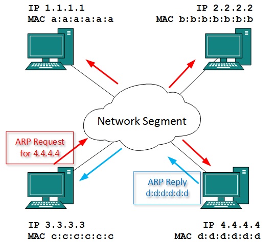
To know the MAC address of remote host on a broadcast domain, a computer wishing to initiate communication sends out an ARP broadcast message asking, “Who has this IP address?” Because it is a broadcast, all hosts on the network segment (broadcast domain) receive this packet and process it. ARP packet contains the IP address of destination host, the sending host wishes to talk to. When a host receives an ARP packet destined to it, it replies back with its own MAC address.
Once the host gets destination MAC address, it can communicate with remote host using Layer-2 link protocol. This MAC to IP mapping is saved into ARP cache of both sending and receiving hosts. Next time, if they require to communicate, they can directly refer to their respective ARP cache.
Reverse ARP is a mechanism where host knows the MAC address of remote host but requires to know IP address to communicate.
Internet Control Message Protocol (ICMP)
ICMP is network diagnostic and error reporting protocol. ICMP belongs to IP protocol suite and uses IP as carrier protocol. After constructing ICMP packet, it is encapsulated in IP packet. Because IP itself is a best-effort non-reliable protocol, so is ICMP.
Any feedback about network is sent back to the originating host. If some error in the network occurs, it is reported by means of ICMP. ICMP contains dozens of diagnostic and error reporting messages.
ICMP-echo and ICMP-echo-reply are the most commonly used ICMP messages to check the reachability of end-to-end hosts. When a host receives an ICMP-echo request, it is bound to send back an ICMP-echo-reply. If there is any problem in the transit network, the ICMP will report that problem.
Internet Protocol Version 4 (IPv4)
IPv4 is 32-bit addressing scheme used as TCP/IP host addressing mechanism. IP addressing enables every host on the TCP/IP network to be uniquely identifiable.
IPv4 provides hierarchical addressing scheme which enables it to divide the network into sub-networks, each with well-defined number of hosts. IP addresses are divided into many categories:
Class A - it uses first octet for network addresses and last three octets for host addressing
Class B - it uses first two octets for network addresses and last two for host addressing
Class C - it uses first three octets for network addresses and last one for host addressing
Class D - it provides flat IP addressing scheme in contrast to hierarchical structure for above three.
Class E - It is used as experimental.
IPv4 also has well-defined address spaces to be used as private addresses (not routable on internet), and public addresses (provided by ISPs and are routable on internet).
Though IP is not reliable one; it provides ‘Best-Effort-Delivery’ mechanism.
Internet Protocol Version 6 (IPv6)
Exhaustion of IPv4 addresses gave birth to a next generation Internet Protocol version 6. IPv6 addresses its nodes with 128-bit wide address providing plenty of address space for future to be used on entire planet or beyond.
IPv6 has introduced Anycast addressing but has removed the concept of broadcasting. IPv6 enables devices to self-acquire an IPv6 address and communicate within that subnet. This auto-configuration removes the dependability of Dynamic Host Configuration Protocol (DHCP) servers. This way, even if the DHCP server on that subnet is down, the hosts can communicate with each other.
IPv6 provides new feature of IPv6 mobility. Mobile IPv6 equipped machines can roam around without the need of changing their IP addresses.
IPv6 is still in transition phase and is expected to replace IPv4 completely in coming years. At present, there are few networks which are running on IPv6. There are some transition mechanisms available for IPv6 enabled networks to speak and roam around different networks easily on IPv4. These are:
- Dual stack implementation
- Tunneling
- NAT-PT
The transmission Control Protocol (TCP) is one of the most important protocols of Internet Protocols suite. It is most widely used protocol for data transmission in communication network such as internet.
Features
TCP is reliable protocol. That is, the receiver always sends either positive or negative acknowledgement about the data packet to the sender, so that the sender always has bright clue about whether the data packet is reached the destination or it needs to resend it.
TCP ensures that the data reaches intended destination in the same order it was sent.
TCP is connection oriented. TCP requires that connection between two remote points be established before sending actual data.
TCP provides error-checking and recovery mechanism.
TCP provides end-to-end communication.
TCP provides flow control and quality of service.
TCP operates in Client/Server point-to-point mode.
TCP provides full duplex server, i.e. it can perform roles of both receiver and sender.
Header
The length of TCP header is minimum 20 bytes long and maximum 60 bytes.

Source Port (16-bits) - It identifies source port of the application process on the sending device.
Destination Port (16-bits) - It identifies destination port of the application process on the receiving device.
Sequence Number (32-bits) - Sequence number of data bytes of a segment in a session.
Acknowledgement Number (32-bits) - When ACK flag is set, this number contains the next sequence number of the data byte expected and works as acknowledgement of the previous data received.
Data Offset (4-bits) - This field implies both, the size of TCP header (32-bit words) and the offset of data in current packet in the whole TCP segment.
Reserved (3-bits) - Reserved for future use and all are set zero by default.
Flags (1-bit each)
NS - Nonce Sum bit is used by Explicit Congestion Notification signaling process.
CWR - When a host receives packet with ECE bit set, it sets Congestion Windows Reduced to acknowledge that ECE received.
ECE -It has two meanings:
If SYN bit is clear to 0, then ECE means that the IP packet has its CE (congestion experience) bit set.
If SYN bit is set to 1, ECE means that the device is ECT capable.
URG - It indicates that Urgent Pointer field has significant data and should be processed.
ACK - It indicates that Acknowledgement field has significance. If ACK is cleared to 0, it indicates that packet does not contain any acknowledgement.
PSH - When set, it is a request to the receiving station to PUSH data (as soon as it comes) to the receiving application without buffering it.
RST - Reset flag has the following features:
It is used to refuse an incoming connection.
It is used to reject a segment.
It is used to restart a connection.
SYN - This flag is used to set up a connection between hosts.
FIN - This flag is used to release a connection and no more data is exchanged thereafter. Because packets with SYN and FIN flags have sequence numbers, they are processed in correct order.
Windows Size - This field is used for flow control between two stations and indicates the amount of buffer (in bytes) the receiver has allocated for a segment, i.e. how much data is the receiver expecting.
Checksum - This field contains the checksum of Header, Data and Pseudo Headers.
Urgent Pointer - It points to the urgent data byte if URG flag is set to 1.
Options - It facilitates additional options which are not covered by the regular header. Option field is always described in 32-bit words. If this field contains data less than 32-bit, padding is used to cover the remaining bits to reach 32-bit boundary.
Addressing
TCP communication between two remote hosts is done by means of port numbers (TSAPs). Ports numbers can range from 0 – 65535 which are divided as:
- System Ports (0 – 1023)
- User Ports ( 1024 – 49151)
- Private/Dynamic Ports (49152 – 65535)
Connection Management
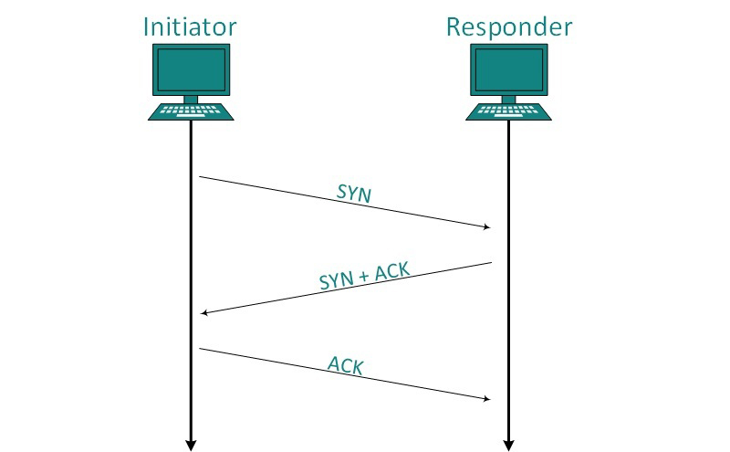
TCP communication works in Server/Client model. The client initiates the connection and the server either accepts or rejects it. Three-way handshaking is used for connection management.
Establishment
Client initiates the connection and sends the segment with a Sequence number. Server acknowledges it back with its own Sequence number and ACK of client’s segment which is one more than client’s Sequence number. Client after receiving ACK of its segment sends an acknowledgement of Server’s response.
Release
Either of server and client can send TCP segment with FIN flag set to 1. When the receiving end responds it back by ACKnowledging FIN, that direction of TCP communication is closed and connection is released.
Bandwidth Management
TCP uses the concept of window size to accommodate the need of Bandwidth management. Window size tells the sender at the remote end, the number of data byte segments the receiver at this end can receive. TCP uses slow start phase by using window size 1 and increases the window size exponentially after each successful communication.
For example, the client uses windows size 2 and sends 2 bytes of data. When the acknowledgement of this segment received the windows size is doubled to 4 and next sent the segment sent will be 4 data bytes long. When the acknowledgement of 4-byte data segment is received, the client sets windows size to 8 and so on.
If an acknowledgement is missed, i.e. data lost in transit network or it received NACK, then the window size is reduced to half and slow start phase starts again.
Error Control &and Flow Control
TCP uses port numbers to know what application process it needs to handover the data segment. Along with that, it uses sequence numbers to synchronize itself with the remote host. All data segments are sent and received with sequence numbers. The Sender knows which last data segment was received by the Receiver when it gets ACK. The Receiver knows about the last segment sent by the Sender by referring to the sequence number of recently received packet.
If the sequence number of a segment recently received does not match with the sequence number the receiver was expecting, then it is discarded and NACK is sent back. If two segments arrive with the same sequence number, the TCP timestamp value is compared to make a decision.
Multiplexing
The technique to combine two or more data streams in one session is called Multiplexing. When a TCP client initializes a connection with Server, it always refers to a well-defined port number which indicates the application process. The client itself uses a randomly generated port number from private port number pools.
Using TCP Multiplexing, a client can communicate with a number of different application process in a single session. For example, a client requests a web page which in turn contains different types of data (HTTP, SMTP, FTP etc.) the TCP session timeout is increased and the session is kept open for longer time so that the three-way handshake overhead can be avoided.
This enables the client system to receive multiple connection over single virtual connection. These virtual connections are not good for Servers if the timeout is too long.
Congestion Control
When large amount of data is fed to system which is not capable of handling it, congestion occurs. TCP controls congestion by means of Window mechanism. TCP sets a window size telling the other end how much data segment to send. TCP may use three algorithms for congestion control:
Additive increase, Multiplicative Decrease
Slow Start
Timeout React
Timer Management
TCP uses different types of timer to control and management various tasks:
Keep-alive timer:
This timer is used to check the integrity and validity of a connection.
When keep-alive time expires, the host sends a probe to check if the connection still exists.
Retransmission timer:
This timer maintains stateful session of data sent.
If the acknowledgement of sent data does not receive within the Retransmission time, the data segment is sent again.
Persist timer:
TCP session can be paused by either host by sending Window Size 0.
To resume the session a host needs to send Window Size with some larger value.
If this segment never reaches the other end, both ends may wait for each other for infinite time.
When the Persist timer expires, the host re-sends its window size to let the other end know.
Persist Timer helps avoid deadlocks in communication.
Timed-Wait:
After releasing a connection, either of the hosts waits for a Timed-Wait time to terminate the connection completely.
This is in order to make sure that the other end has received the acknowledgement of its connection termination request.
Timed-out can be a maximum of 240 seconds (4 minutes).
Crash Recovery
TCP is very reliable protocol. It provides sequence number to each of byte sent in segment. It provides the feedback mechanism i.e. when a host receives a packet, it is bound to ACK that packet having the next sequence number expected (if it is not the last segment).
When a TCP Server crashes mid-way communication and re-starts its process it sends TPDU broadcast to all its hosts. The hosts can then send the last data segment which was never unacknowledged and carry onwards.

