Theoretical Paper
- Computer Organization
- Data Structure
- Digital Electronics
- Object Oriented Programming
- Discrete Mathematics
- Graph Theory
- Operating Systems
- Software Engineering
- Computer Graphics
- Database Management System
- Operation Research
- Computer Networking
- Image Processing
- Internet Technologies
- Micro Processor
- E-Commerce & ERP
Practical Paper
Industrial Training
GIF File Format
Displaying GIF Images
GIF is CompuServe's standard for defining generalized color raster images. This 'Graphics Interchange Format' (GIF) allows high-quality, high-resolution graphics to be displayed on a variety of graphics hardware and is intended as an exchange and display mechanism for graphics images. The image format described below is designed to support current and future image technology.
The main focus of this specification is to provide the technical information necessary for a programmer to implement GIF encoders and decoders. The GIF data format and its components that apply to all GIF decoders is described below.
Graphics Interchange Format Data Definition
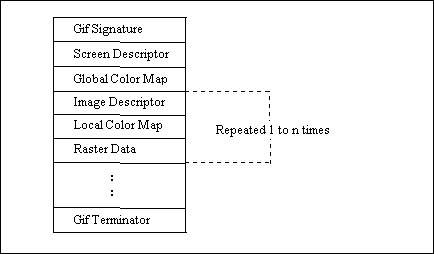
Figure 1
The general file format of GIF is displayed in the above Figure. Lets discuss the features one by one.
GIF Signature
The following GIF Signature identifies the data following as a valid GIF image stream. It consists of the following six characters:
G I F 8 7 a
The last three characters '87a' may be viewed as a version number for this particular GIF definition and will be used in general as a reference in documents regarding GIF that address any version dependencies.
Screen Descriptor
The Screen Descriptor describes the overall parameters for all GIF images following. It defines the overall dimensions of the image space or logical screen required, the existence of color mapping information, background screen color, and color depth information.
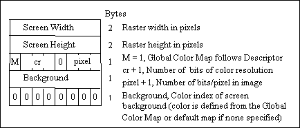
Figure 2
This information is stored in a series of 8-bit bytes as described in the above Figure.
The logical screen width and height can both be larger than the physical display. How images larger than the physical display are handled is implementation dependent and can take advantage of hardware characteristics (e.g. Macintosh scrolling windows). Otherwise images can be clipped to the edges of the display.
The value of 'pixel' also defines the maximum number of colors within an image. The range of values for 'pixel' is 0 to 7 which represents 1 to 8 bits. This translates to a range of 2 (B & W) to 256 colors. Bit 3 of byte 5 is reserved for future definition and must be zero.
Global Color Map
The Global Color Map is optional but recommended for images where accurate color rendition is desired. The existence of this color map is indicated in the 'M' field of byte 5 of the Screen Descriptor. A color map can also be associated with each image in a GIF file as described later. However this global map will normally be used because of hardware restrictions in equipment available today. In the individual Image Descriptors the 'M' flag will normally be zero. If the Global Color Map is present, it's definition immediately follows the Screen Descriptor. The number of color map entries following a Screen Descriptor is equal to 2 raise to power number of bits per pixel, where each entry consists of three byte values representing the relative intensities of red, green and blue respectively. The structure of the Color Map block is shown in the following Figure:
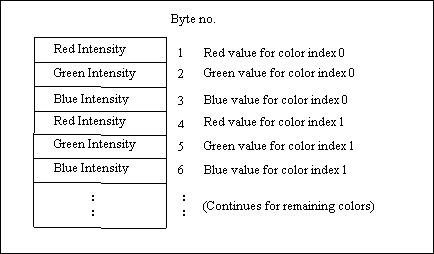
Figure 3
Each image pixel value received will be displayed according to its closest match with an available color of the display based on this color map. The color components represent a fractional intensity value from none (0) to full (255). White would be represented as (255, 255, 255), black as (0,0,0) and medium yellow as (180,180,0). For display, if the device supports fewer than 8 bits per color component, the higher order bits of each component are used. In the creation of a GIF color map entry with hardware supporting fewer than 8 bits per component, the component values for the hardware should be converted to the 8-bit format with the following calculation:
map_value = component_value * 255 / 2 raise to power nbits - 1
This assures accurate translation of colors for all displays. In the cases of creating GIF images from hardware without color palette capability, a fixed palette should be created based on the available display colors for that hardware. If no Global Color Map is indicated, a default color map is generated internally which maps each possible incoming color index to the same hardware color index modulo n where n is the number of available hardware colors.
Image Descriptor
The Image Descriptor defines the actual placement and extents of the following image within the space defined in the Screen Descriptor. Also defined are flags to indicate the presence of a local color lookup map, and to define the pixel display sequence. Each Image Descriptor is introduced by an image separator character. The role of the Image Separator is simply to provide a synchronization character to introduce an Image Descriptor. This is desirable if a GIF file happens to contain more than one image. This character is defined as 0x2C hex or ',' (comma). When this character is encountered between images, the Image Descriptor will follow immediately.
Any characters encountered between the end of a previous image and the image separator character are to be ignored. This allows future GIF enhancements to be present in newer image formats and yet ignored safely by older software decoders.
The format of image descriptor is shown in the following Figure.
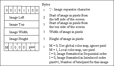
Figure 4
The specifications for the image position and size must be confined to the dimensions defined by the Screen Descriptor. On the other hand it is not necessary that the image fill the entire screen defined.
Local Color Map
A Local Color Map is optional and defined for future use. If the 'M' bit of byte 10 of the Image Descriptor is set, then a color map follows the Image Descriptor that applies only to the following image.
At the end of the image, the color map will revert to that defined after the Screen Descriptor. Note that the 'pixel' field of byte 10 of the Image Descriptor is used only if a Local Color Map is indicated. This defines the parameters not only for the image pixel size, but determines the number of color map entries that follow. The bits per pixel value will also revert to the value specified in the Screen Descriptor when processing of the image is complete.
Raster Data
The format of the actual image is defined as the series of pixel color index values that make up the image. The pixels are stored left to right sequentially for an image row. By default each image row is written sequentially, top to bottom. In the case that the Interlace or 'I' bit is set in byte 10 of the Image Descriptor then the row order of the image display follows a four-pass process in which the image is filled in by widely spaced rows. The first pass writes every 8th row, starting with the top row of the image window. The second pass writes every eighth row starting at the fifth row from the top. The third pass writes every fourth row starting at the third row from the top. The fourth pass completes the image, writing every other row, starting at the second row from the top.
The image pixel values are processed as a series of color indices, which map into the existing color map. The resulting color value from the map is what is actually displayed. This series of pixel indices, the number of which is equal to image-width*image-height pixels, are passed to the GIF image data stream one value per pixel, compressed and packaged according to a version of the LZW compression algorithm as defined in Appendix C.
Gif Terminator
In order to provide a synchronization for the termination of a GIF image file, a GIF decoder will process the end of GIF mode when the character 0x3B hex or ';' is found after an image has been processed. By convention the decoding software will pause and wait for an action indicating that the user is ready to continue. This may be a carriage return entered at the keyboard or a mouse click. For interactive applications this user action must be passed on to the host as a carriage return character so that the host application can continue. The decoding software will then typically leave graphics mode and resume any previous process.
Gif Extension Blocks
To provide for orderly extension of the GIF definition, a mechanism for defining the packaging of extensions within a GIF data stream is necessary. Specific GIF extensions are to be defined and documented by CompuServe in order to provide a controlled enhancement path. GIF Extension Blocks are packaged in a manner similar to that used by the raster data though not compressed. The basic structure is shown in the following Figure:
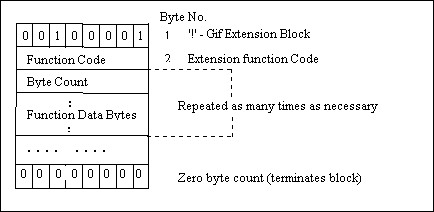
Figure 5
A GIF Extension Block may immediately precede any Image Descriptor or occur before the GIF Terminator. All GIF decoders must be able to recognize the existence of GIF Extension Blocks and read past them if unable to process the function code. This ensures that older decoders will be able to process extended GIF image files in the future, though without the additional functionality.
Raster Data
The Raster Data stream that represents the actual output image can be represented as shown in the following Figure:
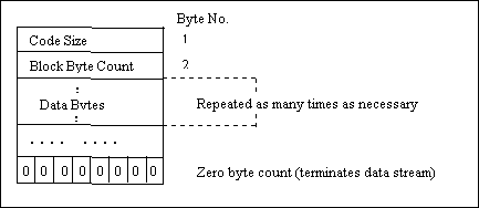
Figure 6
The conversion of the image from a series of pixel values to a transmitted or stored character stream involves several steps. In brief these steps are:
(a) Establish the Code Size - Define the number of bits needed to represent the actual data.
(b) Compress the Data - Compress the series of image pixels to a series of compression codes.
(c) Build a Series of Bytes - Take the set of compression codes and convert to a string of 8-bit bytes.
(d) Package the Bytes - Package sets of bytes into blocks preceded by character counts and output.
Establish Code Size
The first byte of the GIF Raster Data stream is a value indicating the minimum number of bits required to represent the set of actual pixel values. Normally this will be the same as the number of color bits. Because of some algorithmic constraints however, black & white images, which have one color bit must be indicated as having a code size of 2.This code size value also implies that the compression codes must start out one bit longer.
Compression
The LZW algorithm converts a series of data values into a series of codes, which may be raw values or a code designating a series of values. Using text characters as an analogy, the output code consists of a character or a code representing a string of characters.
The LZW algorithm used in GIF matches algorithmically with the standard LZW algorithm with the following differences:
- (a) A special Clear code is defined which resets all compression / decompression parameters and tables to a start-up state. The value of this code is 2 raise to power code size. For example, if the code size indicated is 4 (image is 4 bits/pixel), the Clear code value would be 16 (10000 binary). The Clear code can appear at any point in the image data stream and therefore requires the LZW algorithm to process succeeding codes as if a new data stream was starting. Encoders should output a Clear code as the first code of each image data stream.
(b) An End of Information code is defined that explicitly indicates the end of the image data stream. LZW processing terminates when this code is encountered. It must be the last code output by the encoder for an image. The value of this code is Clear code +1.
(c) The first available compression code value is Clear code + 2.
(d) The output codes are of variable length, starting at code size + 1 bits per code, up to 12 bits per code. This defines a maximum code value of 4095 (hex FFF). Whenever the LZW code value would exceed the current code length, the code length is increased by one. The packing / unpacking of these codes must then be altered to reflect the new code length.
Build 8-Bit Bytes
Because the LZW compression used for GIF creates a series of variable length codes, of between 3 and 12 bits each, these codes must be reformed into a series of 8-bit bytes that will be the characters actually stored or transmitted. This provides additional compression of the image. The codes are formed into a stream of bits as if they were packed right to left and then picked off 8 bits at a time to be output. Assuming a character array of 8 bits per character and using 5 bit codes to be packed, an example layout would be similar to as shown in the following Figure:

Figure 7
Note that the physical packing arrangement will change as the number of bits per compression code change but the concept remains the same.
Package the Bytes
Once the bytes have been created, they are grouped into blocks for output by preceding each block of 0 to 255 bytes with a character count byte. A block with a zero byte count terminates the Raster Data stream for a given image. These blocks are what are actually output for the GIF image. This block format has the side effect of allowing a decoding program the ability to read past the actual image data if necessary by reading block counts and then skipping over the data.
Multiple Image Processing
Since a GIF data stream can contain multiple images, it is necessary to describe processing and display of such a file. Because the image descriptor allows for placement of the image within the logical screen, it is possible to define a sequence of images that may each be a partial screen, but in total fill the entire screen. The guidelines for handling the multiple image situation are as follows:
(1) There is no pause between images. Each is processed immediately as seen by the decoder.
- (2) Each image explicitly overwrites any image already on the screen inside of its window. The only screen clears are at the beginning and end of the GIF image process. See discussion on the GIF terminator.

